Hello everyone,
This is my first post here after acquiring lightly used Audio Institute's VR-110. I'm coming from listening solid state amps (Teac A-H500) for years so I don't have any reference to tube amp background at all.
I felt like buying 2nd hand lightly used tube amp was perfect base platform for me to learn and improve upon so hope to hear back from anyone with good recommendation/suggestion this amp.
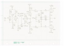
To do this, I've recaptured the circuit and attached here for review so please feel free to comment on any area of circuit that can be further improved. The voltages labeled are actual measurement with DC meter while playing the music so hopefully it's helpful to understanding the circuit better.
The part that I haven't finished is power supply section which will be shared later in time but just wanted to pass along pre-amp/driver circuit diagram to receive initial feedback.
Thanks,
Seon
This is my first post here after acquiring lightly used Audio Institute's VR-110. I'm coming from listening solid state amps (Teac A-H500) for years so I don't have any reference to tube amp background at all.
I felt like buying 2nd hand lightly used tube amp was perfect base platform for me to learn and improve upon so hope to hear back from anyone with good recommendation/suggestion this amp.
To do this, I've recaptured the circuit and attached here for review so please feel free to comment on any area of circuit that can be further improved. The voltages labeled are actual measurement with DC meter while playing the music so hopefully it's helpful to understanding the circuit better.
The part that I haven't finished is power supply section which will be shared later in time but just wanted to pass along pre-amp/driver circuit diagram to receive initial feedback.
Thanks,
Seon
Attachments
Missing the information on the output transformer and the screen grid connection for the 6550's. Do you have the cathode voltage readings for the output tubes?
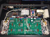
Hi Jabo8, I believe screens grid on 6550 PP was running with +415V (UL connection) and cathode was around -43V (as well as grid, pin-5). Attached is picture of the amp with some modification added such as 6550 B+ timer delay (1-min.) connectors for wires so it's easy to remove main board for any changes in the future.
You might have noticed that few caps are missing since I'm working on twisting heater wires as recommended by many members here.
Thanks,
Seon
You might have noticed that few caps are missing since I'm working on twisting heater wires as recommended by many members here.
Thanks,
Seon
Attachments
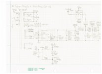
Also just completed power supply schematic capture last night so wanted share it here as well. One thing that I thought was interesting with current setup is that main AC is tabbed from 340V rather than 360V which is unused. Wouldn't 360V AC better suited for 6550 PP output but I'm plan to roll either EL34/6L6/5881 in the futures so not sure if that makes any different here.
Attachments
According to the schematic, the cathodes are only 10 Ohms away from ground.
The grids may be at -43V, but the cathodes are very close to ground.
i.e. If the cathode current is 60mA, the cathodes will be at 60mV.
Again, what is the cathode voltage?
The grids may be at -43V, but the cathodes are very close to ground.
i.e. If the cathode current is 60mA, the cathodes will be at 60mV.
Again, what is the cathode voltage?
Let me double check that voltage level and will get back to you later today. BTW, is there any improvements can be done on pre-amp/inverter & driver stages? Both grid stopper and grid resistor to GND is missing so wondering if this is really needed for 6N3P NOS tubes.
Thanks,
Seon
Thanks,
Seon
You do need a grid input resistor; I might use 100k or 270k Ohm to ground across the input connector, and 1k Ohm grid stopper from there to the input grid (1k right at the grid connection. The resistor values depend on what will drive the input, and the tube specs for maximum grid resistor value, tube capacitance, miller effect, etc. (I am not familiar with that tube).
The amp schematic above from someone else is just like what I do sometimes, leave something out.
But am I always thankful for those who take the time to draw and share schematics, even if there are errors. It is so much easier to see what the amp is, instead of reading text.
The amp schematic above from someone else is just like what I do sometimes, leave something out.
But am I always thankful for those who take the time to draw and share schematics, even if there are errors. It is so much easier to see what the amp is, instead of reading text.
Again, what is the cathode voltage?
It was ~0.5V for 6550 and ~0.4V for 5881WXT.
Did you confirm that the output is ultra-linear? In any case, both readings seem a bit on the low side, e.g., 50mA for the 6550 where as the datasheet suggests 75mA.
The g1 to ground ( R25) should be 50k not 100k. Exceeding 50k in a fixed bias will
run the tube outside spec and risk destructive current runaway.
A concertina phaseinverter is inherently symmetric, and less complicated then the LTP
used.
run the tube outside spec and risk destructive current runaway.
A concertina phaseinverter is inherently symmetric, and less complicated then the LTP
used.
Forget to put the heater circuits to ground ?
If you only cut the HT for the final stage, all the rest wil get the max.supply voltage as with allmost no load !
Mona
If you only cut the HT for the final stage, all the rest wil get the max.supply voltage as with allmost no load !
Mona
Did you confirm that the output is ultra-linear? In any case, both readings seem a bit on the low side, e.g., 50mA for the 6550 where as the datasheet suggests 75mA.
I confirmed that it's operating in UL mode and one of my next modification is adding a switch to enable Triode/UL modes. The main power transformer output current rating was 500mA for 360v/340v/10v so not certain if it was enough to increase bias from 50mA to ~70mA like you suggested.
Thanks,
Seon
50mA should be sufficient for the job unless you run the amp at full blast for a long time, turning the bias up will get you a bit more Class A output, which is always a good thing. From the GE datasheet:

Thanks for your suggestions and it appears that I was under biasing output tubes then. Would you also recommend to run 5881WXT bias higher too since I'm running at 0.35V (35mA). I never turn up my volume very high so it sounds like I'll be alright.
5881WXT is basically the Russian 6P3S-E, which has much lower ratings than the 6550, thus not really a good candidate for tube rolling, perhaps KT88, EL34 would be better choices.
A concertina phaseinverter is inherently symmetric, and less complicated then the LTP
used.
There's no free lunch. The Concertina has the worst PSRR of all phase inverters. Good PSRR is a great advantage of the completely symmetric design the OP is showing to us.
IMHO there's barely room for any improvement, besides the missing (does it really?) 1st tube's grid resistor and perhaps replacing R17 by a solid state CCS.
Best regards!
IMHO there's barely room for any improvement, besides the missing (does it really?) 1st tube's grid resistor and perhaps replacing R17 by a solid state CCS.
It really does missing grid resistor and stopper in this amp design. Could it be the fact that gain of 6N3P is much lower than 12AX7 hence it's less susceptible to noise/oscillation. I would imagine line-out from my DAC (optical-to-line) to amp is sufficient so maybe it won't hurt to add in input stage. Any recommendation on values for 6N3P tube?
In regards to replacing R17 with CCS, is there any good example circuit that I can reference too.
Thanks for great advise.
Omitting the grid resistor simply is a coarse design flaw. One is advised better not to rely on a DC coupled preamplifier output without DC offset.
Besides that, this symmetric design appears perfect to me. With respect to the value of the plate resistors, the 'tail' is quite a bit short, what yet has been stated (or mentioned, at least) by me. A high impedance CCS will address a LTP's asymmetrical behaviour in a perfect manner.
Best regards!
Besides that, this symmetric design appears perfect to me. With respect to the value of the plate resistors, the 'tail' is quite a bit short, what yet has been stated (or mentioned, at least) by me. A high impedance CCS will address a LTP's asymmetrical behaviour in a perfect manner.
Best regards!
Last edited:
So I switched over to 360V secondary and my B+ is increased by 20V to +440V from +420V (from 340V sec.). Subsequently the LTP and driver tubes plate voltages increased from ~135V to ~150V respectively so I'm just wondering if 6N3P tubes can handle the increased plate voltages or not.
According to the datasheet typ. anode voltage is 150V and max. 300V so it should be fine, right?
According to the datasheet typ. anode voltage is 150V and max. 300V so it should be fine, right?
This is very informative if you use google translate....how to mod a tac 34! like a vr110 or affordable valve companies el34 dark....
TAC 34 buizenversterker upgraden of modden - forum.zelfbouwaudio.nl
TAC 34 buizenversterker upgraden of modden - forum.zelfbouwaudio.nl
- Status
- Not open for further replies.
- Home
- Amplifiers
- Tubes / Valves
- Audio Institute VR-110 schematic review