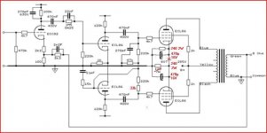
I've have the abovementioned amp on my bench for repair. But I don't have a lot of experience finding the cause of problems in other amps than my own. But I'm keen to learn. 🙂
1.) Swapped the tube. The problems stays in the same socket.
2.) Nothing looks burnt.
3.) Screen resistor is good and is connected to the socket.
4.) Output transformer primary measure the same value in both output transformers.
5.) I removed coupling cap to the grid. No change. So no bad capacitor.
6.) Pulled the tube from the socket where the issue is...and measured b+ looks ok around 280.
7.) Cathode is connected to the shared cathode resistor and that checks out. 120R.
8.) Haven't measured the grid leak resistor yet...'t was too late in the AM so I went to bed.
But I'm stumped at the moment because everything checks out good so far.
I'm guessing the problem must be in the preceding stage i.e. the phase splitter?
Any other causes of red plate?
Attachments
Last edited:
You can work back from the symptom. Red plate means too much anode current. Too much anode current means either wrong grid bias or (possibly) strong oscillation. As you have tried removing the coupling cap, it can't be the previous stage.
An open circuit grid leak resistor will do it, or a bad connection on the grid socket of the valve holder. Surface leakage (due to solder flux or just general dirt) on the valveholder can do it too.
An open circuit grid leak resistor will do it, or a bad connection on the grid socket of the valve holder. Surface leakage (due to solder flux or just general dirt) on the valveholder can do it too.
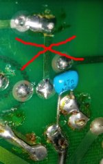
Thanks for the suggestions. The socket on that tube is dirtier and generally looks worse than the others. Solder flux was also not cleaned from the circuit board after the modifications the owner had done (not by me).
Wanted to clean it up but was too lazy to go downstairs to fetch the circuit board cleaning spray can.
Can't wait to clean it up tonight and measure the grid leak.
Cheers.
Wanted to clean it up but was too lazy to go downstairs to fetch the circuit board cleaning spray can.
Can't wait to clean it up tonight and measure the grid leak.
Cheers.
Not my amp. And no requirements by the guy who brought it to me.Now you'r at it, perhaps some changes (for the better ?)
But thanks for the suggestion. I would probably also would have done that it if it was mine. 😀
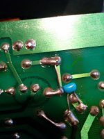
Fixed. Just started to check continuity from the grid leak resistor. From the coupling capacitor to the grid stopper there was no connection. I find it hard to tell what is what with a circuit board. Anyway fixed. Thanks!
Attachments
- Status
- Not open for further replies.