- It looks as if the trace from pin 11 is crossing the traces from pins 13 and 14, leading to shorts.
- There is nothing connected to pin 4. How are you going to unmute the amp?
- Are you going to take a wire for every single ground connection to the star point? It would be easier to connect ground groups on the board and only take two wires to the star point.
- Did you check the trace widths for current capability? That is especially important for the power supply and speaker traces.
- Did you check component sizes? It is hard to believe that a 2,2 µ 10 V electrolytic cap should have the same footprint as a 2200 µ 25 V electrolytic cap.
- You should leave a bit more space in between the components for ease of mounting and soldering and for component cooling.
Thank you for your reply !
The trace from pin 11 is crossing the traces from pins 13 and 14, leading to shorts may be need to redraw it as Diptrace is not showing any shorts.
I keep pin 4 non-connected as I don't like to use mute. I don't know how to unmute the amp can you tell me ?
What is the star point that you mean ?
The trace width for current flow is keept for upto 1 amp current flow only as if need in future I will add 0.025 point to make it wider.
Component sizes are great headache for my amp as I like to keep size of PCB within 2" X 2" maximum due to space.
If pin 4 is not connected, the amp won't play. According to the schematic you posted you need to connect a 5 V signal through a 10 K resistor to pin 4.I keep pin 4 non-connected as I don't like to use mute. I don't know how to unmute the amp can you tell me ?
The point where all ground connections meet. Normally either on the power supply board next to the smoothing caps or on the case where the PE enters.What is the star point that you mean ?
20 W into 4 Ohm correspond to 2,2 A. 20 W into 8 Ohm correspond to 1,6 A.The trace width for current flow is keept for upto 1 amp current flow only as if need in future I will add 0.025 point to make it wider.
You won't get rid of the headache by drawing components smaller than they actually are. It will also not help, if solder pins overlap with components or are so near to each other that you cannot solder them without producing a short.Component sizes are great headache for my amp as I like to keep size of PCB within 2" X 2" maximum due to space.
Pacificblue,
Thank you for your reply !
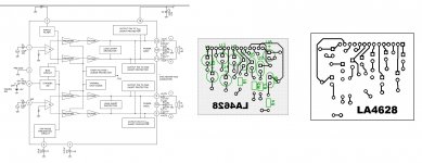
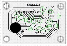
Here it is the revised PCB of LA4628 as per your advices for you judging it.
Again Thank you !
Thank you for your reply !
Here it is the revised PCB of LA4628 as per your advices for you judging it.
Again Thank you !
Attachments
Last edited:
Interesting star point. You can make that much smaller. Add a solder point to it where you can connect the wire from the power supply.
I don't think your amp will play when pin 4 is connected to ground through a resistor. The datasheet sepcifies a 5 V signal there.
You still use the same sizes for all caps. U1 and U4 seem to slightly overlap. U3 looks as if it could be overlapping with the amp chip.
I don't think your amp will play when pin 4 is connected to ground through a resistor. The datasheet sepcifies a 5 V signal there.
You still use the same sizes for all caps. U1 and U4 seem to slightly overlap. U3 looks as if it could be overlapping with the amp chip.
I don't think your amp will play when pin 4 is connected to ground through a resistor. The datasheet sepcifies a 5 V signal there.
How I can add a 5v signal in pin 4 ? Can you tell me ?
You don't need a 5 V signal at pin 4. You need a signal of 1,5 zo 3 V. The datasheet shows how to achieve that with a 5 V input. For a higher supply voltage you need to increase the series resistor.
You could use a trimmer, set it to the highest resistance, connect one end to the supply voltage and the wiper to pin 4. Turn it slowly down until the amp switches on. Then measure the resistance that is set on the trimmer and replace the trimmer with a resistor of the next lower value.
Depending on the supply voltage the trimmer should have 100k up to ~18 V supply voltage. More, if the supply voltage is higher.
pixnum; You need to look at the data sheets for these chips, thay will tell you all you need to know. The books that just post schematics from the data sheets without any explanations on how thay work either assume you have some back ground or are vary poor sources of information.Andy
- Status
- Not open for further replies.
- Home
- Amplifiers
- Chip Amps
- Audio Amplifier LA4628