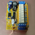
I've bought this relay attenuator module from aliexpress. It seems to work as advertised. However, I'd like to change the resistors so its 10K rather than 50K.
Then I realised I'm not actually sure how it works at all - there are only 10 resistors. Can anyone show me a similar circuit?
the resistor values are 420k - 180k - 75k - 30k - 12k - 4.7k - 1.8k - 670R. Near the input is a 50k and near the output is a 42R
with thanks
James
Then I realised I'm not actually sure how it works at all - there are only 10 resistors. Can anyone show me a similar circuit?
the resistor values are 420k - 180k - 75k - 30k - 12k - 4.7k - 1.8k - 670R. Near the input is a 50k and near the output is a 42R
with thanks
James
Attachments
Last edited:
According to the product description, it combine 1-3 resistors for R1 and 1-5 resistors for R2 to form an attenuator.

.png")
Ah great, I didn't see that. This might take some reverse engineering. I'm tempted just to divide scale all the values though. Any idea what the 42r on the output would do?
The 50K probably defines the input impedance and the 42R the output impedance, but you need to find or make a schematic.
A schematic would confirm that you just need to divide all resistors by 5.
420k /5 = 8.4K
180k /5 = 36K
75k /5 = 15K
30k /5 = 6K
12k /5 = 2.4K
4.7k /5 = 940
1.8k /5 = 360
670 /5 = 134
Years ago, I played with resistor ladders. You probably want log ( ~1dB) steps which means you need to cascade binary value attenuators with constant in and out impedance. A spread sheet is your best tool today to make a ladder with 1, 2, 4, 8, ....128 dB steps. At work, I used a multiplying DAC for a telephony gadget, and while a log device existed, I got the +/- 15dB values I needed from a common linear part. But it all becomes a moot point if you just do your preamp functions in software.
Thanks. Do you have any guess what the 42r near the output would do?A schematic would confirm that you just need to divide all resistors by 5.
420k /5 = 8.4K
180k /5 = 36K
75k /5 = 15K
30k /5 = 6K
12k /5 = 2.4K
4.7k /5 = 940
1.8k /5 = 360
670 /5 = 134
Years ago, I played with resistor ladders. You probably want log ( ~1dB) steps which means you need to cascade binary value attenuators with constant in and out impedance. A spread sheet is your best tool today to make a ladder with 1, 2, 4, 8, ....128 dB steps. At work, I used a multiplying DAC for a telephony gadget, and while a log device existed, I got the +/- 15dB values I needed from a common linear part. But it all becomes a moot point if you just do your preamp functions in software.
Err, it defines the output impedance? As already suggested? But no firm answers without a schematic.
Is that 1dB change in voltage, power, “loudness”. I’m looking at a similar problem. To be linear in loudness you need to take quite large steps in voltage.You probably want log ( ~1dB) steps
The first two are the same, and there is no such thing as a 'loudness' decibel.Is that 1dB change in voltage, power, “loudness”.
Let’s forget about dB for now, I guess what’s I’m saying is that in circuits it’s much easier to relate everything to a voltage, for ease of probing or calculation etc. So you could arrange you steps to be linear in voltage, a voltage step that gives a linear change in power, or a voltage step that attempt to give a linear change in the perceived loudness. It’s evident these are not the same. I agree the last is pretty ill defined, but could be approximated.
I was just wondering if there is a standard way of calculating for that, and what makes most sense for a stepped volume control.
I was just wondering if there is a standard way of calculating for that, and what makes most sense for a stepped volume control.
I don’t know what you mean by sound power, power delivered to the speaker?
We are actually agreeing with each other.
Power is exponential (well actually quadratic) with respect to voltage. So you need to take non-linear steps in voltage to give linear steps in power.
A nice attenuator should feel linear to the user. I’m just trying to ask the standard way people do this. Or maybe they don’t.
Sound power is exponential, so how is this linear?
We are actually agreeing with each other.
Power is exponential (well actually quadratic) with respect to voltage. So you need to take non-linear steps in voltage to give linear steps in power.
A nice attenuator should feel linear to the user. I’m just trying to ask the standard way people do this. Or maybe they don’t.

The original purpose of the unit we now call "dB" was not about how we hear. It was "mile of cable", the loss in a mile of a specified telephone cable. Briefly called "TU" (transmission unit). This became a real thing; there were even artificial "mile of cable"s smaller than an actual mile-reel. Meanwhile in another part of Bell Labs pundits were pondering perception, realized that the MoC/TU was a very useful unit, and also that it was very close to a simple 10*log() expression, and that the base unit could be named after Alex Bell.can't 'forget about dB for now'
This all made more sense when the slide-rule was the badge of the trade.
Bells or deci-Bells is a power ratio. A deci-Bell is the smallest change in loudness that a human can detect so attenuator steps smaller than 1dB are not useful.
https://en.wikipedia.org/wiki/Decibel
Plus one Decibel is a power ratio of 1.2589 or 125.1% and minus one is the reciprocal. That means a Voltage ratio of 1.122 or 112.2% and -1bB is 89.125% Voltage.
In electronics, there are standard power levels dBm = 1 milliWatt and dBu = 1 microWatt. and these are often used loosely to refer to standard voltages into standard impedances, 600 Ohms for dBm and 50 Ohms for dBu, even when the circuit impedance is something else. This happens a lot in audio where impedance in and out often do not match. Where cables are less than a mile long, they are much shorter than audio frequency wavelengths so there is not the need for impedance matching. dBV is used to specify a voltage with respect to 1 Volt, regardless of the impedance. dBA is an acoustic sound pressure where zero is the level below which it is inaudible, and sound power requires an area over which that sound pressure is applied or a distance from the source given that sound pressure falls based on the inverse square law. In the telecom and DSP business, expressions like dB0, dBm and dBOV refer to -6dB (half voltage) below clipping, 1mW (~0.7746Vrms) and the level where the analog signal is square wave clipped. A typical RCA "aux input" is -20dB, ie about 70mV and a microphone is -40dBV to -60dBV (1mV). An op-amp based mixer/preamp that runs on +/-15VDC is capable of 10Vrms = +20dBV output.
The 42 Ohm resistance may be a buffer build-out or part of the attenuator. With only 10 resistors, this attenuator must use a lot of compromises, perhaps very clever and perhaps not. We can only speculate, not having one to reverse engineer, nor any schematic etc. I could not find the product description that chrisng mentions?
Maybe in RF (and maybe as "dBuV"). In audio, dBu seems to be co-opted for "unterminated"; i.e. the 600r 0.775V convention but not actually driving 600r.dBu = 1 microWatt
I don't cite Wikipedia as "authority" but just a starter-list of all the ways we abuse the language.
https://en.wikipedia.org/wiki/Decibel#Voltage
Hi James,I've bought this relay attenuator module from aliexpress. It seems to work as advertised. However, I'd like to change the resistors so its 10K rather than 50K.
Then I realised I'm not actually sure how it works at all - there are only 10 resistors. Can anyone show me a similar circuit?
the resistor values are 420k - 180k - 75k - 30k - 12k - 4.7k - 1.8k - 670R. Near the input is a 50k and near the output is a 42R
with thanks
James
I also bought this attenuator but the 10K version, the only difference in resistance is that mine has 2*10K and yours 2*50K
Regards,
Miguel
Get ready to be hotly debated by "golden ears" who are deeply offended by that statement 😉Bells or deci-Bells is a power ratio. A deci-Bell is the smallest change in loudness that a human can detect so attenuator steps smaller than 1dB are not useful.
https://en.wikipedia.org/wiki/Decibel
Hey!!! You dissing our beloved slide rules?This all made more sense when the slide-rule was the badge of the trade.
Remember that even Isaac Asimov depicted 31st Century Astrogators calculating interstellar trajectories on slide rules!!!!
And they never ever missed Trantor on their way back!!!!

No. How did you read that in my words?Hey!!! You dissing our beloved slide rules?
I am dissing people who don't know slide-rules.
Ever heard of tongue-in-cheek? 😉
https://dictionary.cambridge.org/us/dictionary/english/tongue-in-cheek
Well, that 🙂
https://dictionary.cambridge.org/us/dictionary/english/tongue-in-cheek
Well, that 🙂
- Home
- Source & Line
- Analog Line Level
- Attenuator resistor calculations