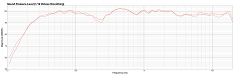
I just completed ATC SCM100 speakers with Scanspeak tweeter. I measured the frequency response and there is a dip at 250 Hz (crossover point is 770Hz. What could be causing this?
What is your room size? How microphone and speaker were positioned? Have you measured with MLS or Sine?
It looks like you measurements are affected by room or speaker/microphone position.
Can you make nearfield measurements?
Not to nitpick but if you have ATC SCM100 the crossover point should be 380Hz.
With a different crossover you have a different speaker using the same drivers.
The drop at 250Hz looks like floor bounce to me.
With a different crossover you have a different speaker using the same drivers.
The drop at 250Hz looks like floor bounce to me.
I measured in the room and then took the speakers outside to measure (on lawn). The dip was apparent in all measurements from different positions, different locations and I even tried different amplifiers. I used a 10sec sine sweep. I did not know the crossover point for ATC's were 350Hz. The guy I bought the crossovers from said that thay were different from the standard ATC's but I did not expect the crossover point to be so different.
Is it possible that this is the actual frequency responce of the bass driver and this is the reason they crossed it at 350hz?
Also, one question I did not answer, I measured different distances from half meter to 2 meters from the speaker but the response was similar.
Also, one question I did not answer, I measured different distances from half meter to 2 meters from the speaker but the response was similar.
One more thing, I tested the ATC's alongside some Zaph ZRT's that I built previously, and the respons from the ZRT's at same position and same measurement method was flat, so that kind of rules out the possibility of environment or measurement issues.
One of 3 things I'd guess, if crossed at 250 the woofer polarity could be reversed, floor bounce or baffle diffraction.
I'm a bit a loss here.
The woofer crosses at 770 so it's not polarity, Beiteltjie excluded floor bounce since he measured them under a variety of conditions with the same result and baffle step should affect everything below a certain frequency.
Could there be a notch filter hidden in the xover?
It's not standard and may be the previous owner was addressing some problems he had in his room.
then he could measure the driver near field (.5" or 12mm for the rest of the world). Then you could tell for sure if it's the crossover or something else. Wouldn't have to measure any other driver except the woofer if crossed at 770.
I checked the polarity by swapping the bass driver phase, but then a dip appeared at 770Hz as expected, so the phase is correct. The crossovers are newly made so unlikely contains a notch filter. Judging by the components is does not look like it either.
It boggles the mind!
It boggles the mind!
Definitely.
The only way to really know if it's the woofer or something else.
Also it would be quite interesting in itself to have the FR of an ATC woofer.
So please let us know once you do the test and also exactly which version of woofer it is ie the commercially available short- and long-coil ones or the SL which ATC do not usually sell to the public.
Beiteltjie,
what does the filter schematic look like and how did you dampen the
box inside? Try measuring the impedance of the whole speaker.
what does the filter schematic look like and how did you dampen the
box inside? Try measuring the impedance of the whole speaker.
Lojzek, I will have to ask the guy who buit the crossovers for the schematics. He supplied the drivers with crossovers to me. Regarding the box, it is 106 liters, well braced with 25mm compressed fibreglass on sides and 50mm on bottom, top and rear. Nothing on baffle.
Unfortunately, I had to deliver the speakers as the guy was keen to get them. I will have to get them back to measure again but it won't be this weekend.
Unfortunately, I had to deliver the speakers as the guy was keen to get them. I will have to get them back to measure again but it won't be this weekend.
Just a thought:
Is it possible that whoever built that crossover assumed that the mid is 8Ohm while it is 16?
That would shift at least one aspect of the crossover by one octave and 770Hz is not far off from being an octave higher than 380.
AS I said just a thought since I am far from competent when it comes to passive xovers.
Very good point! The guy did mention that the mid resistance was not the standard one. I will follow up with him.
- Status
- Not open for further replies.
- Home
- Loudspeakers
- Multi-Way
- ATC SCM100 frequency response