At what voltage and frequency defining the OPT's leakage inductance ?
Measuring Leakage Inductance Lsp is usually defined as shorting the secondary and measuring the inductance on the primary winding.
However, Lsp is strongly dependent on applied voltage and frequency as shown in the attachement.
When a transformers primary inductance Lp is specified at 230V@50Hz, it will simply not be possible to use this same voltage and frequency with a shorted secondary winding because it will blow the OPT into pieces.
Nevertheless, to calculate the quality factor, one has to know the corresponding Lsp because Qf = Lp/Lsp.
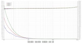
In the attachment below, several Lsp measurements are shown measured with a VNA with three different voltages, resp 1Vpp, 2Vpp and 4Vpp, resulting at 50Hz in resp 31.9mH, 22,5mH and 15.2mH.
So, Lsp is inversely proportional to the applied voltage, almost with the square root.
Going upwards in frequency all curves are coming together independent of applied voltage, resp 1.55mH@500Hz, 1.15mH@5Khz and 1.15mH@50Khz.
Interpolating this from 4Vpp to 230Vrms would result in 1.19mH at 230V, but how far off can this be ?
Hans
Measuring Leakage Inductance Lsp is usually defined as shorting the secondary and measuring the inductance on the primary winding.
However, Lsp is strongly dependent on applied voltage and frequency as shown in the attachement.
When a transformers primary inductance Lp is specified at 230V@50Hz, it will simply not be possible to use this same voltage and frequency with a shorted secondary winding because it will blow the OPT into pieces.
Nevertheless, to calculate the quality factor, one has to know the corresponding Lsp because Qf = Lp/Lsp.
In the attachment below, several Lsp measurements are shown measured with a VNA with three different voltages, resp 1Vpp, 2Vpp and 4Vpp, resulting at 50Hz in resp 31.9mH, 22,5mH and 15.2mH.
So, Lsp is inversely proportional to the applied voltage, almost with the square root.
Going upwards in frequency all curves are coming together independent of applied voltage, resp 1.55mH@500Hz, 1.15mH@5Khz and 1.15mH@50Khz.
Interpolating this from 4Vpp to 230Vrms would result in 1.19mH at 230V, but how far off can this be ?
Hans
Attachments
I didn't dig up too much into leakage inductance dependecy on frequency, although it could be possible that it might be true to an extent. I tend to get practical in the terms of leakage inductance, that is, how much of a roll-off does it bring for an audio transformer. Here is an easy step.
1. Measure the frequency transformer under various conditions to identify resonant frequencies, the peak and the dip resonance. Write down their locations.
2. Measure another frequency with a loaded secondary and the lowest driving impedance possible. I do that with 50R, so that we isolate capacitance as roll-off determining factor.
3. Tweak your frequency load so that you get the roll-off far away from resonances. Then capture the -3dB roll-off. I'm lazy on math, so I recreate my transformer model in LTSpice with only primary and secondary ohmic losses and added leakage inductance value until I get the same roll-off. The added inductance in the LTSpice model is your leakage inductance value.
50AE, thx for replying.
You seem to assume that there is only one value for Lsp, you may be right, but that doesn’t seem to be the case looking at my VNA measurements.
If so it would be easy to simply use an inductance meter with shorted secondary.
Hans
You seem to assume that there is only one value for Lsp, you may be right, but that doesn’t seem to be the case looking at my VNA measurements.
If so it would be easy to simply use an inductance meter with shorted secondary.
Hans
In this application note from OnSemi, Christophe Basso defines his method for determining leakage inductance. https://www.onsemi.com/pub/Collateral/AN1679-D.PDF
This. App Note also determines Lps by measuring the inductance on the primary side while shorting the secondary side.In this application note from OnSemi, Christophe Basso defines his method for determining leakage inductance. https://www.onsemi.com/pub/Collateral/AN1679-D.PDF
The original question still remains, at what voltage and what frequency.
Hans
The leakage inductance of an OT only matters at high frequencies where it represents a significant series impedance.
At low frequencies its impedance is negligible and has no effect on PT performance.
At low frequencies its impedance is negligible and has no effect on PT performance.

Rikaro, please read my posting #1.
My question concerns the Quality factor Qf = Lp/Lps.
For this calculation you can’t use 230V@50Hz for measuring Lp and a high frequency and a low voltage for Lps.
You have to compare apples to apples.
Hans
My question concerns the Quality factor Qf = Lp/Lps.
For this calculation you can’t use 230V@50Hz for measuring Lp and a high frequency and a low voltage for Lps.
You have to compare apples to apples.
Hans
Both Lp and Lps vary with voltage and frequency - but differently.My question concerns the Quality factor Qf = Lp/Lps.
For this calculation you can’t use 230V@50Hz for measuring Lp and a high frequency and a low voltage for Lps.
So Lp/Lps is far from being a fixed number - rather it depends on voltage and frequency as well.
Why do you need it?
Last edited:
Both Lp and Lps vary with voltage and frequency - but differently.
So Lp/Lps is far from being a fixed number - rather it depends on voltage and frequency as well.
Why do you need it?
When a supplier specifies a figure for Qf, where Lp is measured at 230V@50Hz it is interesting to know how he got the corresponding Lsp value.
Hans
In principle, the leakage inductance is mostly dependent on the geometric/configuration of the windings; the core should play a minor role, except for certain arrangements, like side by side coils.
The shorted winding "hides" the core from the test winding, but at low frequencies where the ohmic copper resistance begins to matter compared to the reactances, the "hiding" becomes imperfect and the test winding sees the core and its added inductance (heavily shunted by the copper resistance), thus increasing the apparent leakage inductance.
When the core comes into play, all its non-linearities also appear, explaining the level dependence of the value.
All of this is relatively insignificant, since the leakage inductance mostly matters at higher frequencies
Exactly, Elvee. This is the reason I'm measuring Ls from the high frequency response practical significance only, I don't find it necessary to theoretically dig into the LF domain.
One could also remove the core, if it "gets in the way".
One could also remove the core, if it "gets in the way".
I've used a soundcard and REW to generate an impedance plot of the primary, with shorted secondaries, for assessing leakage inductance of PP output transformers. I'd suggest choosing 1kHz as a nominal reporting frequency for the calculated leakage inductance.
Above 1kHz, the impedance magnitude starts to rise as phase shifts away from resistive, towards the first self resonance (circa 50kHz for an example Partridge WWFB), although the calculated leakage inductance was fairly constant up to about 20kHz. Although the magnitude and phase are fairly constant down to below 10Hz, the calculated leakage inductance slowly increased below 1kHz, and was double by 50Hz.
That impedance plot can also calculate the effective winding capacitance after the resonance, and that capacitance value was the same when derived from an impedance plot of an open secondary (ie. just measuring the primary winding). Given that the winding capacitance and leakage inductance are of most interest for assessing higher frequency resonance behaviour, I didn't try to change applied test voltage for measuring leakage inductance.
From an historical perspective, I'd suggest the leakage inductance would have been measured on a bridge at either 1kHz or 10kHz, and from what I've measured I'd suggest they would give the same nominal inductance.
Certainly measuring the open primary inductance is quite dependent on excitation voltage, but that's not this thread's topic.
Ref doc for leakage inductance plots at: https://www.dalmura.com.au/static/Williamson output transformer measurements.pdf
Lots of answers but unfortunately none of them addresses my question concerning a supplier’s specified quality factor Qf for an OPT where only Lp is mentioned to be measured at 230V@50Hz but no further details are given at what voltage and frequency Lsp is measured or even interpolated.
I know Qf is just a figure, but without a good definition it has little meaning, that’s why.
Hans
I know Qf is just a figure, but without a good definition it has little meaning, that’s why.
Hans
Agree that Qf is of little use here.I know Qf is just a figure, but without a good definition it has little meaning, that’s why.
Other manufacturers like Hammond do specify Lsp at 1V/1kHz..
What Lsp do you calculate from the manufacturer's Lp and Qf numbers?
At 1V/1Khz I measure 1.15mH while the specs mentions a value of 2.16mH.
With a measured Lp of 550H this would result in a Qf = 550/1.15e-3 = 478,000.
Twice as high as the specced 225,000.
Hans
With a measured Lp of 550H this would result in a Qf = 550/1.15e-3 = 478,000.
Twice as high as the specced 225,000.
Hans
The so-called Q is not extremely relevant on its own: it is more a figure of merit reflecting the quality of the construction and the materials.
For a design, what matters is the magnetizing inductance and the leakage inductance on their own, rather than their ratio. Of course, the higher the better, but the value cannot be used directly in a design, AFAIK
For a design, what matters is the magnetizing inductance and the leakage inductance on their own, rather than their ratio. Of course, the higher the better, but the value cannot be used directly in a design, AFAIK
A higher Q suggest better properties, but wen not properly defined, it becomes completely meaningless.it is more a figure of merit reflecting the quality of the construction and the materials.
Hans
- Home
- Amplifiers
- Tubes / Valves
- At what voltage and frequency defining the OPTs leakage inductance