I have an "Astronic Audio Response Equaliser type A1671", 60's model I think, could someone help me with connecting this up for electric guitar recording please.
It has 9 bands & on the rear panel there are two connecting sockets one has 18 pins & the other has 4. I dont' have the connecting plugs but can work around that.
Not sure how to connect this properly?
It has an on/off switch as well as a in/out switch & a Level Pot, there is also a red light so it seems to require power?
I have attached a very poor picture of the same model I found on the Internet.
Cheers
Attachments
Get someone to take a picture of the inside with the cover off otherwise we do not have much to work with.
Offhand I would say you would need a preamp to go between your guitar and the input as the equalizer is a low impedance and your guitar is high impedance. You might be able to use a foot pedal as the interface.
Offhand I would say you would need a preamp to go between your guitar and the input as the equalizer is a low impedance and your guitar is high impedance. You might be able to use a foot pedal as the interface.
Thanks for the reply Printer2,
A Pre Amp or a Footpedal is no problem as I have a few.
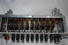
I removed the top & bottom covers from the unit & took a couple of pictures, attached. You can't see much from them without dismantling the entire unit.
I spent some time working out the schematic for it & have attached that as well, if anyone can understand it. I'm sure everyone will let me know if I buggered it up🙂
On the far left is the sliding selector mechanism, up near the top of this I have marked the contact poles A & B & this corresponds to A & B marked on the schematic.
The sliding selectors are in contact with the B side all the time & the A side of it will contact either one or two single poles at once.
At the top right of the schematic there is the 18 pin socket numbered accordingly, these numbers also correspond to the numbers on the schematic. Just down from the top of the schematic itself you will see where I have numbered some wires that run to the 18 pin socket.
Eg, numbers 1 2 3 4 etc on the schematic go to pins 1 2 3 4 etc on the socket.
I did this so the schematic was not so cluttered.
For the small circuit wired to the 18 pin socket, the two resistors represent a pot & I couldn't find a switch in the program so I just drew a rough switch, it's a two position switch, either one way or the other.
There is another 4 pin socket on the rear of the unit but after having a look these are just for lighting up the red light on the front panel & serve no other purpose?
Not sure why they put it there to start with, the device needs no power as far as I can see.
Now, how to wire this sucker up to use it??
Also can someone give me a brief or otherwise explanation of how this unit works, I was expecting to see more components inside, not just resistors.
Do these just attenuate varying frequencies😕
Cheers
A Pre Amp or a Footpedal is no problem as I have a few.
I removed the top & bottom covers from the unit & took a couple of pictures, attached. You can't see much from them without dismantling the entire unit.
I spent some time working out the schematic for it & have attached that as well, if anyone can understand it. I'm sure everyone will let me know if I buggered it up🙂
On the far left is the sliding selector mechanism, up near the top of this I have marked the contact poles A & B & this corresponds to A & B marked on the schematic.
The sliding selectors are in contact with the B side all the time & the A side of it will contact either one or two single poles at once.
At the top right of the schematic there is the 18 pin socket numbered accordingly, these numbers also correspond to the numbers on the schematic. Just down from the top of the schematic itself you will see where I have numbered some wires that run to the 18 pin socket.
Eg, numbers 1 2 3 4 etc on the schematic go to pins 1 2 3 4 etc on the socket.
I did this so the schematic was not so cluttered.
For the small circuit wired to the 18 pin socket, the two resistors represent a pot & I couldn't find a switch in the program so I just drew a rough switch, it's a two position switch, either one way or the other.
There is another 4 pin socket on the rear of the unit but after having a look these are just for lighting up the red light on the front panel & serve no other purpose?
Not sure why they put it there to start with, the device needs no power as far as I can see.
Now, how to wire this sucker up to use it??
Also can someone give me a brief or otherwise explanation of how this unit works, I was expecting to see more components inside, not just resistors.
Do these just attenuate varying frequencies😕
Cheers
Attachments

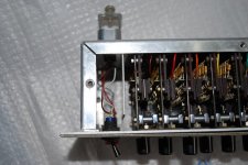

Hate to be the bearer of bad news but but you have a nine channel resistive divider network. The slider is a big switch and you have a resistor ladder network attached to it. Each card I would guess goes out to your multi pin connector. This module is to be interfaced with some on board electronics on the board.
You have a rack of precision sliders, not much use unless you wanted to build the electronics to go with it. Not that that is practical.
You have a rack of precision sliders, not much use unless you wanted to build the electronics to go with it. Not that that is practical.
Thanks Printer2,
Now I can see what it is, no problems as I got it for nothing, do you think I could make it into a Decade box of sorts or is it useful as another piece of test equipment maybe?
I couldn't see how it could work as an equaliser, that's why I asked.
Cheers
Now I can see what it is, no problems as I got it for nothing, do you think I could make it into a Decade box of sorts or is it useful as another piece of test equipment maybe?
I couldn't see how it could work as an equaliser, that's why I asked.
Cheers
Thanks Printer2,
Now I can see what it is, no problems as I got it for nothing, do you think I could make it into a Decade box of sorts or is it useful as another piece of test equipment maybe?
I couldn't see how it could work as an equaliser, that's why I asked.
Cheers
At best I could see them being 2% resistors but probably 5%. Now days 1% is common so if you need a decade box you can build one for not much coin. The question is what you need to do what you want not can I do something with this.
Basically they are a rack of level controls. If you have a use for some and they fit the bill then they are useful. If not then they are just a relic from the past.
Thanks Printer2,
Yeah, I guess your right, i'll have a think, seems a pity to throw it in the corner as a relic from the past.
I will have a use for it i'm sure.
I am a Luthier of about 30 years & am setting up some recording gear among many other things.
Cheers
Yeah, I guess your right, i'll have a think, seems a pity to throw it in the corner as a relic from the past.
I will have a use for it i'm sure.
I am a Luthier of about 30 years & am setting up some recording gear among many other things.
Cheers
Last edited:
Astronic 'Response Control'
I remember these from the 60's - the active electronics were in a separate box connected by a multi-cable 'umbilical'. I guess the idea was to make panel mounting easier.
Found a nice front panel shot here:
Adrian Utley: Recording Third
I remember these from the 60's - the active electronics were in a separate box connected by a multi-cable 'umbilical'. I guess the idea was to make panel mounting easier.
Found a nice front panel shot here:
Adrian Utley: Recording Third
I just stumbled across the original circuit diagram for this unit. You are missing the input transformer, input amp, gain stage, output amp and output transformer. Sadly and most importantly the unit is full of inductors one per frequency band. I believe the specification for the inductors is on the circuit diagram.
I will get it scanned in and uploaded at some point over the next week if you are still interested...
I will get it scanned in and uploaded at some point over the next week if you are still interested...
Hi Chris,I just stumbled across the original circuit diagram for this unit. You are missing the input transformer, input amp, gain stage, output amp and output transformer. Sadly and most importantly the unit is full of inductors one per frequency band. I believe the specification for the inductors is on the circuit diagram.
I will get it scanned in and uploaded at some point over the next week if you are still interested...
Are you still an active member on here? I am very interested in the Astronic A1671 Equaliser.
Best regards,
Graham
- Home
- Live Sound
- Instruments and Amps
- Astronic Equaliser type a1671