Member
Joined 2009
Paid Member
For bass and mid bass horns, BLH’s and their like, undersizes mouths are often unavoidable. The horns behave more like a TL at their cut-off and their impedance becomes very peaky.
Reading about how the k-tube works to distribute resonances along the tube I was wondering if cutting slots in the last section of a horn mouth would help smooth out the biggest (lowest freq) impedance bump that is a consequence of an under-sized horn mouth most often necessary for home use bass horns.
For example, take a 2.5 metre long horn and put slots in the last 0.5m
I'd be more concerned about the FR than the electrical impedance in & of itself, since they are both consequences of the same acoustical impedance mismatch.
Be that as it may, yes, to an extent at least. A similar principle is sometimes applied to gun barrels, although it needs careful design & measurement. Fulmer's patent as I recall included a similar approach, albeit with a series of drilled holes rather than slots.
Be that as it may, yes, to an extent at least. A similar principle is sometimes applied to gun barrels, although it needs careful design & measurement. Fulmer's patent as I recall included a similar approach, albeit with a series of drilled holes rather than slots.
Member
Joined 2009
Paid Member
Do you have a reference to this patent, I found one but the 'tuning holes' are buried deep within, and even better, do you know of anybody who implemented Fulmer's idea and reported on the results, as that would be great corroboration ?
FR - yes, this is a trade-off I accept and somewhat ignore with the expectation that the 'room' will make a dogs dinner of the response at the lowest freq. anyway
FR - yes, this is a trade-off I accept and somewhat ignore with the expectation that the 'room' will make a dogs dinner of the response at the lowest freq. anyway
Attachments
Last edited:
Not off the top of my head other than pointing you toward Sapkowski's (not especially original) 1996 patent. Variations of Fulmer's first design & those using an array of expanding holes / slots to reduce pressure were lurking in the '60s however.
If you're ignoring that, you might as well ignore the electrical too, since they are both results of the same cause. Unless you're running a current source amplifier, in which case flattening the electrical impedance may be beneficial if you are still happy to accept the acoustic issues.
If you're ignoring that, you might as well ignore the electrical too, since they are both results of the same cause. Unless you're running a current source amplifier, in which case flattening the electrical impedance may be beneficial if you are still happy to accept the acoustic issues.
hi Bigun, I meant to reply the question on slots and effect upon horn/driver input impedance is something I can't directly answer/nor know.
Are you talking about the upper input impedance peaks? - or fundamental? - and are the horns in question front loaded with a back chamber?
I once slotted a 10 ft long t-line for about 24 inches of its final travel. That resulted in a larger terminus, higher tuning, plus introduced a dip in the response. It might be like trying with bad eyesight to level a chair, chopping blindly on one leg at a time as when the slot is significant, a small mouth horn's path will shorten - just a general guess.
With a given horn, a driver with low Q vs one with moderate and both with similar Vas, the low Q driver can have a smaller back chamber and more output til the LF knee. (plus the tight back chamber will limit excursion below cutoff.
Bill Fitzmaurice's horns typically have long path's vs mouth size as does the old Vitavox "Thunderbolt". La Scala has.a relatively short path.
Hi Moose - Fulmer's published pipe had the organ pipe slot, the patent dealt with possibility of using distributed holes. Sapkowski's holey pipe is interesting - almost bet without damping material a lot of mids would leak from those holes.
I'm trying to get my blood sugar down - so far not moving much below 3X 100 for a week w. pills - doesn't help with pea-brain
(not sure why Imgur seems to change URL to something not easily accessed - ?)
Impedance sweeps:
Klipschorn pulled from the corner vs snugged into the corner
https://i.imgur.com/PB969I9.gif
RCA-Fan 7 cubic foot bulk mid bass horn
https://i.imgur.com/hrQQLys.jpg
Picture of RCA-Fan horn
https://i.imgur.com/a2EYtXQ.jpg
Sim of Vitavox Thunderbolt horn scaled 0.7 times
https://i.imgur.com/9zoai8A.jpg
Sim of Cerwin AB36 scaled to 6 inch driver
https://i.imgur.com/nYFZElK.png
University Sound "Dean" basically has just the fundamental peak
https://i.imgur.com/iu85tsL.jpg
Last edited:
The horns behave more like a TL at their cut-off.....
Reading about how the k-tube works to distribute resonances along the tube I was wondering if cutting slots in the last section of a horn mouth would help smooth out the biggest (lowest freq) impedance bump.....
That's because they are 😉 if not designed 'close enough' a match up to the room's acoustics.
Depends on the section's acoustic length. In short, ideally need to slot/whatever back along its axial length to where it's still horn loaded.
Regardless, when it comes to vented alignments [which all horns are], 'critically' damping the vent is my default 'one size fits all' 😉 acoustic solution to an acoustic problem:
Click test: Click Test | GM210 | Flickr
GM
Member
Joined 2009
Paid Member
Thanks gents.
I plan to build a FLH using a 15” woofer PD.153C001
Nominal design: length is 2.5m to 2.7m (sorry for the metric units, I’m talking Canadian to a Brit and an American!), throat at approx 1/3 Sd and of course the mouth is too small at =< 4000 sq.cm. with a desire to squeeze down to 60Hz and down as little as possible at 40Hz and good up to 300Hz. Exponential flare.
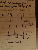
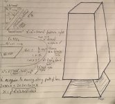
Exponential mid-bass inspired by Tune Audio Anima, which means it’s down-firing so that brings in some questions of it’s own no doubt. Single fold, driver sits on the floor and fires up, single fold turns it back down to exit on the floor.
It’s my first horn build, first foray into Hornresp and just in that place where you have to hold your nose at the whole idea of it being a TL more than a horn...and thinking about additional ideas applicable to undersized horn mouths.
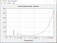
The sims show those TL ripples, not dissimilar to your posting of the Fan 7.
I plan to build a FLH using a 15” woofer PD.153C001
Nominal design: length is 2.5m to 2.7m (sorry for the metric units, I’m talking Canadian to a Brit and an American!), throat at approx 1/3 Sd and of course the mouth is too small at =< 4000 sq.cm. with a desire to squeeze down to 60Hz and down as little as possible at 40Hz and good up to 300Hz. Exponential flare.
Exponential mid-bass inspired by Tune Audio Anima, which means it’s down-firing so that brings in some questions of it’s own no doubt. Single fold, driver sits on the floor and fires up, single fold turns it back down to exit on the floor.
It’s my first horn build, first foray into Hornresp and just in that place where you have to hold your nose at the whole idea of it being a TL more than a horn...and thinking about additional ideas applicable to undersized horn mouths.
The sims show those TL ripples, not dissimilar to your posting of the Fan 7.
Last edited:
Floor loading allows a decent tuning option, especially if a phase plug is used to alter the flare rate ['S' or 'T'], so will fan out abruptly near the mouth. IOW, better for LF to use hyperbolic flare, then the open area around it ideally needs to be at least ~34400/pi/[~110*0.81] = 122.98 Hz = ~89 cm dia. = ~6226.88 cm^2 and ideally ~34400/pi/30.78 Hz = ~3511.07 cm dia. = ~15696019.1 cm^2 😉, so how much ~unobstructed floor space is there and will it be near/up against a wall or corner?
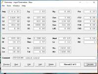
Based on published specs and assuming only default 0.5 ohm [Rs]:
Fhm = 2*38/0.239 = ~318 Hz = the highest that can be compression horn/box loaded
Flc = Fs*0.239/2 = ~4.54 Hz = lowest
Qts' = Qts + any added series resistance [Rs]: HiFi Loudspeaker Design
This wide a BW ideally needs a ~610.97 cm^2 throat, but must shrink it to a 3.6:1 CR and use a large rear chamber [reducing compression loading] to meet your 2.7m/4k cm^2 [Sm] at very low 'ripple' without resorting to a mouth phase plug, though figure you'll never 'sink' enough power to even heat it up unless max out EQ down low, so shouldn't be a problem.
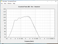
Anyway, near enough unwrinkled ~414.6 L, 0.21 hypex/95 dB/w/m/40 Hz, which can be EQ'd up to ~120 dB/m if need be and have 400 W on tap. 😉
Since I don't know all the variables involved [yet], just a frame of reference sim to compare with, improve upon/scrap/whatever as it's a 'seat of the pants' R-O-T vintage style horn, so if you try to use HR's System Designer to revise it, good luck!
GM
edit: added HR file
Based on published specs and assuming only default 0.5 ohm [Rs]:
Fhm = 2*38/0.239 = ~318 Hz = the highest that can be compression horn/box loaded
Flc = Fs*0.239/2 = ~4.54 Hz = lowest
Qts' = Qts + any added series resistance [Rs]: HiFi Loudspeaker Design
This wide a BW ideally needs a ~610.97 cm^2 throat, but must shrink it to a 3.6:1 CR and use a large rear chamber [reducing compression loading] to meet your 2.7m/4k cm^2 [Sm] at very low 'ripple' without resorting to a mouth phase plug, though figure you'll never 'sink' enough power to even heat it up unless max out EQ down low, so shouldn't be a problem.
Anyway, near enough unwrinkled ~414.6 L, 0.21 hypex/95 dB/w/m/40 Hz, which can be EQ'd up to ~120 dB/m if need be and have 400 W on tap. 😉
Since I don't know all the variables involved [yet], just a frame of reference sim to compare with, improve upon/scrap/whatever as it's a 'seat of the pants' R-O-T vintage style horn, so if you try to use HR's System Designer to revise it, good luck!
GM
edit: added HR file
Attachments
Last edited:
The thing that makes a TL resonance is the sudden opening at the end. A discontinuity. Extra flaring near your mouth can soften this, but you have to trade off. Ie, the importance of the original horn flare at that region vs the axial resonance.
edit: added HR file
Forgot to change Vrc to the large chamber = 103.24 L.
GM
Member
Joined 2009
Paid Member
Extra flaring near your mouth can soften this......
+1 and why I want to know how much 'open enough' floor space is available. 😉
GM
Member
Joined 2009
Paid Member
It's gonna sit on 30cm high legs off the floor. It can be positioned close to a wall, or even in a corner area if beneficial.
I'm not against experimenting or in taking advice in a different direction. Nevertheless, I have cut some wood today to force things forwards or I'll remain an armchair hobbyist. The challenge in making too many experimental cabinets is the difficulty of getting wood - I use 2' x 4' handy panels from Home Depot. They fit nicely in the back of my Corolla. But I cleaned out the local store, with the Pandemic going on their shelves are getting emptier each time I visit.
I'm not against experimenting or in taking advice in a different direction. Nevertheless, I have cut some wood today to force things forwards or I'll remain an armchair hobbyist. The challenge in making too many experimental cabinets is the difficulty of getting wood - I use 2' x 4' handy panels from Home Depot. They fit nicely in the back of my Corolla. But I cleaned out the local store, with the Pandemic going on their shelves are getting emptier each time I visit.
Attachments
Last edited:
The driver, sitting at the bottom and firing up, will form a very basic phase plug
🤐 Didn't visualize it this way! Still had another poster's PVC pipe TL design stuck in my mind.
GM
Member
Joined 2009
Paid Member
Yeah, it’s a kind of giant lava lamp 
Anyhow, I think k slots in the mouth will be an experiment for another day and the ripple in the impedance - will have to be seen if it’s an issue. The wavelengths are long, not sure if I have enough flare at the opening AllanB, will be relying a bit on the pyramid shaped back chamber to help.
Anyhow, I think k slots in the mouth will be an experiment for another day and the ripple in the impedance - will have to be seen if it’s an issue. The wavelengths are long, not sure if I have enough flare at the opening AllanB, will be relying a bit on the pyramid shaped back chamber to help.
Attachments
Last edited:
Both slots and flaring do the same thing, just keep the slots small to a wavelength. The overall flaring has to be large enough to a wavelength to have the desired effect.
Clearly you've put some thought into the shape. Try to keep it smooth enough and consistent where possible, to avoid diverting energy into resonances.
Clearly you've put some thought into the shape. Try to keep it smooth enough and consistent where possible, to avoid diverting energy into resonances.
The slotted mouth horn was invented by Mr. Iwata following his work on the mouths of train tunnels for high speed rail. Invented in the 1960s, I think.
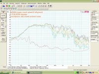
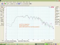
The throat and mouth sizes of your proposed horn are very similar to the sizes of a couple of horns I built, although mine were only 80cm long on one and ~100cm long for a 12" driver.
If you can raise the lower cutoff nearer to 80Hz I don't think you will have much trouble with ripple in the response.
I've attached a couple of plots, one with a EV 15L driver on 80cm length (similar to Edgarhorn), and one with a JBL 2020H driver on ~100cm length.
I'm just respraying the EV 15L ones to use under a 2way MEH project at the moment so might have some better measurements soon (REW rather than just an RTA trace)
Rob.
Attachments
Yeah, it’s a kind of giant lava lamp
Anyhow, I think k slots in the mouth will be an experiment for another day and the ripple in the impedance - will have to be seen if it’s an issue. The wavelengths are long, not sure if I have enough flare at the opening AllanB, will be relying a bit on the pyramid shaped back chamber to help.
Your model is very simple to CAD. Why not use Akabak3 acoustic physics simulator?
Member
Joined 2009
Paid Member
Thx folk,
Rob, good to know I’m in good company. I got some additional confidence this morning from discovering that the ‘big fun horn’ has very similar length and mouth size: bigfunht
Akabak? I heard this is more difficult to use than Hornresp, I will look at this more closely once more construction is progressed and I have time again.
I was thinking, that positioning my horn into a corner will create an extended mouth on the two sides near to and adjacent to the walls. It may behave like an extended fold, with the sound curling out from under the mouth and moving up between the wall and horn enclosure. This extends the length and expansion. The front facing part of the horn plays into the room without nearby walls. Overall, this is like having a giant virtual slot in the horn mouth !
Last edited:
- Home
- Loudspeakers
- Multi-Way
- Assisting Undersized Horn Mouths