Hi.
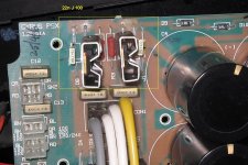
I've just removed the extra paralleled diodes from this Cyrus Amp PSX bridge. They are not needed since the recently installed diodes have much higher ratings than the originals. I decided to fill the vacant space with 22nF caps to reduce noise but are these little polyester caps strong enough? The supply gives out +/- 40V unregulated and has 88000uF. The transformer is 500VA. The caps are rated at 100V but I worry that they might have to dissipate a lot of energy.
What do you think and what happens if they fail? Do they go short or open? I have listened at low levels without problems so far but I'm now feeling nervous.
Please help!!! 😱
Attachments
They will be fine. You can probably improve things by adding series resistance to the caps - it will control the ringing a lot better as well as reduce the energy.
However, you really need to scope the bridge to tune it all correctly.
If they are Schottky diodes you don't even need the caps and should remove them.
However, you really need to scope the bridge to tune it all correctly.
If they are Schottky diodes you don't even need the caps and should remove them.
Thanks Richie. As always you have been very helpful.
I am using BYW80200 200V, 8A, 35ns Fast recovery diodes.
http://www.hificollective.co.uk/pdf/byw80200.pdf
I'll just leave the caps in if they are doing no harm .... at least until I get a decent scope!!!
Thanks again,
Martin.
I am using BYW80200 200V, 8A, 35ns Fast recovery diodes.
http://www.hificollective.co.uk/pdf/byw80200.pdf
I'll just leave the caps in if they are doing no harm .... at least until I get a decent scope!!!
Thanks again,
Martin.
Hi
-100V rating for poly caps in these conditions is way too low (refer to docs by Wima, Rifa, etc). If they fail, they will do so in unpredictable ways, some graceful (capacitance reduction...) or less so (melting, burning).
-Polycaps aren't very effective for removing RF noise (internal impedance too high); ceramic caps are more effective in this respect
-adding a series resistor will ruin their effectiveness in terms of RF suppression and mains modulation removal; it may remove the ringing associated with the inductances of the transformer, but that's another story. If you want both, you'll have to install both.
Conclusion:
replace your caps with the usual 10nF/500V ceramic discs; it will be safer and more effective.
LV
Caps across the bridge is not an appropriate place to attempt mains noise removal, that should be done at the mains input socket before it has a chance to use the internal wiring as antennas.
And as for ruining RFI suppression, if the diode is snubbed properly the RFI problem will practically disappear. Therefore caps (with series resistance) across the bridge, aiming to alleviate the ringing caused by interaction with the transformer inductance is entirely justified.
Those caps will be OK, but it won't hurt to use higher voltage or ceramic ones.
Just to be clear, I'm only using these caps as an easy way to, hopefully, suppress RFI that may be generated specifically by the diodes. I have a mains filter before the transformer and 88000uF capacitance after to alleviate any other problems in theory at least.
I'll whip them out for now until I can replace them with something stronger. So, ceramic caps are preferable for some things then.
Thanks for all the advice,
Martin. 😀
I'll whip them out for now until I can replace them with something stronger. So, ceramic caps are preferable for some things then.
Thanks for all the advice,
Martin. 😀
Hi,
100V caps for 40Vdc is OK. Even if mains voltage goes to max tolerance they are still well in.
What size of fuse is fitted to the primary side?
100V caps for 40Vdc is OK. Even if mains voltage goes to max tolerance they are still well in.
What size of fuse is fitted to the primary side?
Hi Andrew,
Hmmm .... it currently has a T3,15 Amp fuse (3.15 Amp 250V). In a huge supply like this? I don't get it.
The DC rails are fused at 4 amps each. I'll see what's in my C1 and C2. Does that sound a little small to you?
My concern with the small caps was that they would somehow find it difficult to absorb those 'nasty looking' spikes that I had seen depicted on graphs. I guess I worry too much.
In my head I either imagined these spikes as high frequency and low energy artifacts shepherded gently away by the poly caps or horribly spiky and damaging surges relentlessly hitting those poor little plastic caps. You can see that my theoretical ability is not the best!! Is it possible for the caps to pass more CURRENT than they are designed for?
Kind regards,
Martin.
OK ... so I've learned something today:
Mains fuses:
Cyrus One 1A
Cyrus Two 1.15A
Cyrus PSX 3.15A
Mains fuses:
Cyrus One 1A
Cyrus Two 1.15A
Cyrus PSX 3.15A
Hi,
I try to close rate all my fusing.
The idea being that if something is starting to go wrong then little extra current is needed to blow the fuse.
Your 500VA transformer is theoretically able to draw 2.1Aac. The peaks are satisfied by the capacitors.
I would try to fit either T2A or T2.5A, using time delay to allow the transformer to draw it's full rated power.
But the PSX will not start on a T2A fuse. It is unlikely to start on a T2.5A fuse and with the bigger smoothing you have fitted you may get nuisance blowing of the T3.1A.
To close rate you must go to soft start using either a power thermistor or relay bypassed resistor.
I don't want to alarm you, but Elvee's comment prompted my question.
I wonder what it is that he found in the manufacturer's datsheet?If they fail, they will do so in unpredictable ways, some graceful (capacitance reduction...) or less so (melting, burning).
You can find some details here for instance:
http://www.wima.com/EN/flammability.htm
Regarding the voltage rating, a general purpose film cap rated at 100V DC normally withstands 63V AC at low frequencies (not always the case however). That's about 90V peak. In a typical center-tap rectifier, the diode will see a reverse voltage of ~80V peak.
So, OK then?
Not really: each time time the transformer is switched off, a spike will be generated over and above that voltage; the exact magnitude of the spike will depend on a number of uncontrollable factors such as the coupling between the half-secondaries of the transformer, its leakage inductance, the presence or type of a primary mains filter, the precise instant wrt. to 50Hz phase at which the switching off occurs, etc. Typically, the amplitude could be 2 to 3 times the normal peak voltage, but in some cases it can be much higher.
A final word about the role of those caps: if anything, they are not useful for removing mains-borne RFI; one might argue the contrary in fact.
They serve to remove the bursts of RF energy generated each time a diode turns off; even soft-recovery rectifiers generate such bursts, albeit of smaller magnitude.
They also remove the PIN-diode effect from these diodes: when an RF element (such as a tuner) is in the vicinity, their effect is to switch the ground/antenna configuration of the ensemble, producing an annoying 100Hz buzz in the received (or even transmitted) signal.
LV
Hi Elvee,
you have referred us to the wrong document.
That one applies to X & Y rated capacitors across the mains side of the transformer.
We are discussing the caps across the secondary side of the transformer. Do you want to extrapolate some information for us that can be applied to this case? If so you will have to explain it to us in small easy to understand steps.
An inductor will always try to oppose the action by creating a reaction. Simple school physics. Break the current flow and a back emf opposes the action and generates a spark across the (very) high impedance switch contacts.
Put in a bypass, maybe a reversed diode and the back emf is limited to the voltage across the forward biassed diode. The energy in the inductor is now dissipated as current through the diode. Have a look at the diode bypass across a relay coil.
Now consider the secondary of the transformer. The output is terminated with rectifier and smoothing caps and maybe a load and maybe also some RC snubbing. The back emf is limited to the voltage across the caps/load and the energy dissipates as current.
At the input side of the transformer the back emf creates that spark across the now open (high impedance) switch and that's where you would place the spark arresting RC snubber. But again that does not apply to our caps.
you have referred us to the wrong document.
That one applies to X & Y rated capacitors across the mains side of the transformer.
We are discussing the caps across the secondary side of the transformer. Do you want to extrapolate some information for us that can be applied to this case? If so you will have to explain it to us in small easy to understand steps.
what's that got to do with our caps?the diode will see a reverse voltage of ~80V peak
This does not apply to the terminated side of the transformer.each time time the transformer is switched off, a spike will be generated over and above that voltage; the exact magnitude of the spike will depend on a number of uncontrollable factors such as the coupling between the half-secondaries of the transformer, its leakage inductance, the presence or type of a primary mains filter, the precise instant wrt. to 50Hz phase at which the switching off occurs, etc. Typically, the amplitude could be 2 to 3 times the normal peak voltage, but in some cases it can be much higher
An inductor will always try to oppose the action by creating a reaction. Simple school physics. Break the current flow and a back emf opposes the action and generates a spark across the (very) high impedance switch contacts.
Put in a bypass, maybe a reversed diode and the back emf is limited to the voltage across the forward biassed diode. The energy in the inductor is now dissipated as current through the diode. Have a look at the diode bypass across a relay coil.
Now consider the secondary of the transformer. The output is terminated with rectifier and smoothing caps and maybe a load and maybe also some RC snubbing. The back emf is limited to the voltage across the caps/load and the energy dissipates as current.
At the input side of the transformer the back emf creates that spark across the now open (high impedance) switch and that's where you would place the spark arresting RC snubber. But again that does not apply to our caps.
AndrewT said:Hi Elvee,
you have referred us to the wrong document.
That one applies to X & Y rated capacitors across the mains side of the transformer.
We are discussing the caps across the secondary side of the transformer. Do you want to extrapolate some information for us that can be applied to this case? If so you will have to explain it to us in small easy to understand steps.
This document shows what happens when a capacitor of a certain technology is overstressed; X and Y capacitors are ruggedized versions of standard caps. If you stress a mylar X cap and a mylar standard cap, they will fail in similar ways; the only differences are that it will take KVs to destroy the X cap and only hundreds of volts to destroy the standard cap, and that the standard cap will fail in a more catastrophic way than the X cap (which is supposed to be a safety cap).
The cap will be subjected to the same voltage as the diode since it is in parallelwhat's that got to do with our caps?
This is true, I made a mistake on this one, as I considered only a full-wave, center-tap, unipolar supply; in the case of a bipolar supply, the voltage is clamped to the opposite rail (provided the diodes have a fast enough forward-recovery characteristic).This does not apply to the terminated side of the transformer.
An inductor will always try to oppose the action by creating a reaction. Simple school physics. Break the current flow and a back emf opposes the action and generates a spark across the (very) high impedance switch contacts.
Put in a bypass, maybe a reversed diode and the back emf is limited to the voltage across the forward biassed diode. The energy in the inductor is now dissipated as current through the diode. Have a look at the diode bypass across a relay coil.
Now consider the secondary of the transformer. The output is terminated with rectifier and smoothing caps and maybe a load and maybe also some RC snubbing. The back emf is limited to the voltage across the caps/load and the energy dissipates as current.
At the input side of the transformer the back emf creates that spark across the now open (high impedance) switch and that's where you would place the spark arresting RC snubber. But again that does not apply to our caps.
LV
- Status
- Not open for further replies.
- Home
- Amplifiers
- Power Supplies
- Are these caps safe?