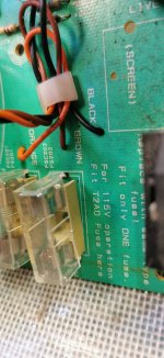
It's not the first time a DIYer has had diffuculty with the internal mains connections for the 115/230V mains supply options in Arcams's Alpha series (I assume that's the A series) models. Of course, a user isn't expected to know that Arcam used the alternate (meaning only 1 fuse is fitted) fuse holders, to select the appropriate mains voltage which is all very clever and maybe saves a few cents but not so nice for DIYs, if you weren't expecting such a strange way of doing things. This is where a full read of the service manual and some earlier threads that explain it and other other common Alpha series problems better and may be helpful.
Last edited:
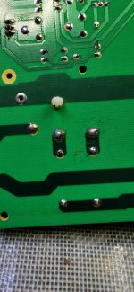
If there's a problem there, it could be due to a manufacturing fault compounded with fiddling about with the fuses by a previous owner or fixer who may not have understood what the instructions meant or whether they applied to the situation. I wasn't suggesting that you misunderstood or had anything to do with it but you did comment on the state of the unused fuse holder connection and your pic shows what looks like poor (no adhesion) soldering. That also looks like its original condition, so any force applied to fit or remove a fuse there, could have led to damage, one way or another.
In particular, it suggests someone may, through unwise fuse fitting, have applied 230V to a single 115V winding. That wouldn't necessarily damage the transformer or its thermal fuse but it could, with virtually double the AC output voltages, have done a lot of damage to the rectifier, main power caps and the amplifier(s) etc, depending on how long the fault voltages were maintained, parts quality and so on. Perhaps do a check on the supply voltages first - no connections to DC loads?
In particular, it suggests someone may, through unwise fuse fitting, have applied 230V to a single 115V winding. That wouldn't necessarily damage the transformer or its thermal fuse but it could, with virtually double the AC output voltages, have done a lot of damage to the rectifier, main power caps and the amplifier(s) etc, depending on how long the fault voltages were maintained, parts quality and so on. Perhaps do a check on the supply voltages first - no connections to DC loads?
Last edited:
https://www.hifiengine.com/manual_library/arcam/alpha-5.shtml
I'm guessing an op-amp in the bass/treble area. However, how do the knobs feel?
Need a rough procedure? Using a test speaker, get a long bit of wire and wrap it around the power lead. This wire is an aerial, picking up 50hz. One end can be put on the output side of a questionable op-amp to see if your test speaker asks for mercy. If it does, you can move to the input side of the op-amp.
You could just tap at the chips legs with a driver, but a 50hz signal from around the lead is a bit stronger. You can test it's strength with the direct switch, sticking it in a relevant socket. Just to be sure it's enough.

actualy im still learning realy repairing amps with differential's so all suggestions welcome, and @Ian Finch , not a probelm, i didnt think you were suggesting anything.
Its my own fault for starting the thread off the way i have so no worries there 😉
Its my own fault for starting the thread off the way i have so no worries there 😉
Im not that familiar yet with the 'direct' feature of these amps.https://www.hifiengine.com/manual_library/arcam/alpha-5.shtml
I'm guessing an op-amp in the bass/treble area. However, how do the knobs feel?
Need a rough procedure? Using a test speaker, get a long bit of wire and wrap it around the power lead. This wire is an aerial, picking up 50hz. One end can be put on the output side of a questionable op-amp to see if your test speaker asks for mercy. If it does, you can move to the input side of the op-amp.
You could just tap at the chips legs with a driver, but a 50hz signal from around the lead is a bit stronger. You can test it's strength with the direct switch, sticking it in a relevant socket. Just to be sure it's enough.
I presume it by passes the tone section and just works flat direct from the volume control?
also if it was an op amp, wouldnt you still have one side working.
the guy who gave me this amp said it would only work on direct(either channel) so it realy needs to be something common to both in my head.
Ill do as i usualy do and start at the power supply and work my way through
Never a bad place to start. I was just looking, and the +/-15v regs are mainly concerned with opamps in the defeated circuits. They have test points before and after them. There only other use seems to an an opamp at the very start of the power section. It's job I'm unclear of, but it doesn't look like it's in the signal path. Some sort of feedback loop. Offset perhaps. I have no idea.
I had a Denon come my way with the same symptoms. I feel somebody probably stuck line level in the phono stage, and took out one a bit further along the line. The phono stage gave up it's chip, which I moved along and fixed it. Minus the phono stage. Which was repurposed as phone not phono, as a bluetooth module was going in.
I had a Denon come my way with the same symptoms. I feel somebody probably stuck line level in the phono stage, and took out one a bit further along the line. The phono stage gave up it's chip, which I moved along and fixed it. Minus the phono stage. Which was repurposed as phone not phono, as a bluetooth module was going in.
As said, it's not hard to trace where a signal (i.e. line level) fault lies.) You just need a steady source signal like from even the crudest of oscillators, sig. generators, anywhere - perhaps from a tuner, another amplifier, tape deck, CD player, PC audio test osc. program etc. but it needs to have a variable level and be electrically isolated or connected safely via a film cap of 0.1uF or somewhat less and rated at a higher peak voltage than possible between any 2 points you might accidentally touch with the probe and ground leads, whether AC or DC.
400 - 630V rating MKT or MKP film types are common and should be OK when connected between any mains powered audio gear on the same AC supply. Otherwise, a small and simple battery operated oscillator is probably safest and some, based on SMD NE555, can be very, as in US$1, cheap and small.
I do like the raw simplicity of friendly1's neatly isolated 50Hz source but personally, I find a standard test frequency of around 400Hz is more easily heard.
The plan is to feed the signal alternately via a probe and fixed input ground connection, to both channel inputs and walk it through the identifiable, successive R & L channel preamp signal nodes and test points according to the schematic, until you get signal back in the fault channel. It's actually common to find faulty, cheap miniature panel switches that have silver plated contacts but no wiping action. That's a bad idea for most low voltage applications because silver tarnishes and eventually stops conducting those small voltages. FWIW, popular Technics amps of the 1980s also had their plated tone control bypass switches fail after less than 10 years and repeatedly at intervals thereafter since you couldn't buy suitable replacements.
Most vertical mosfet or hexfet amplifiers now have (preferably) a Jfet input opamp or comparator working at the input stage as a DC servo controller to sense and maintain a stable DC output offset which is not quite as easy as with BJT designs. Mooly has described the operation rather well in a few mosfet design threads here already.There only other use seems to an an opamp at the very start of the power section. It's job I'm unclear of, but it doesn't look like it's in the signal path. Some sort of feedback loop. Offset perhaps. I have no idea.
Thanks Ian. If my suspicions carry on being correct, a loss of that chip could go unnoticed. It ties things together, though loosing both 15v would be something.
I didn't post before, but wrote out some ideas about physical damage to the switch-gear. Not just aging, but more the result of hitting it harder.
I didn't post before, but wrote out some ideas about physical damage to the switch-gear. Not just aging, but more the result of hitting it harder.
I wouldn't want to lose the servo controller either. Without it, your speakers would eventually, thanks to the likely temp. rise of the amp, be receiving a significant but wandering DC voltage backed by amps of current on tap. So, a DC detect circuit and output relay hopefully comes to the rescue.
For anyone interested in what's expected to happen and how, here's the not-too-long story of DC servo controllers for audio amplifiers, put in reasonably simple words and expression by ESP's Rod Elliott: https://sound-au.com/articles/dc-servo.htm
I'll wait for the OP to comment on the switches as I think he may be able to add some more specific details.
Last edited:
- Home
- Amplifiers
- Solid State
- Arcam 5-working only on direct mode.