Hi I hope you are all well..
Maybe someone could help me with an issue I have with this amplifier. I bought this privately last year. When i checked over the amp at home, one of the screen resistors had blown, I subsequently replaced this 2w 100ohm and fitted new valves and biased them. I also replaced the PS caps.
All has been fine for a few months, however last night the sound distorted then the amp blew its fuse. There was a bad smell of burning, upon inspection V4 and V6 had blown screen resistors and the output transformer on the right hand channel doesn't smell good.
I have basic knowledge in electronics, can use a meter. It could be a scrapper if the OPT is toast but any help welcome.
Attachments
Hopefully it’s the proximity of the blown resistors you smell and not the output transformer (OT). My suggestions for beginning your search:
1. Unplug V4 and V6, and wall power. Measure the resistances of the primary taps of the OT. (CT to both ULs and plates) If you have continuity and resistances are balance around the CT you may be in luck and still have a good OT.
2. Next, with all power tubes/valves out, power up the amp, and measure the relevant power supply voltages. You should be able to find a voltage chart on the AR website to compare you measurements. My theory is that you may have a faulty bias supply.
Good luck!
Did you buy matched output tubes ( from audio research ?) This ampHi I hope you are all well..
Maybe someone could help me with an issue I have with this amplifier. I bought this privately last year. When i checked over the amp at home, one of the screen resistors had blown, I subsequently replaced this 2w 100ohm and fitted new valves and biased them. I also replaced the PS caps.
All has been fine for a few months, however last night the sound distorted then the amp blew its fuse. There was a bad smell of burning, upon inspection V4 and V6 had blown screen resistors and the output transformer on the right hand channel doesn't smell good.
I have basic knowledge in electronics, can use a meter. It could be a scrapper if the OPT is toast but any help welcome.
needs the tubes matched.
Last edited:
Hopefully it’s the proximity of the blown resistors you smell and not the output transformer (OT). My suggestions for beginning your search:
1. Unplug V4 and V6, and wall power. Measure the resistances of the primary taps of the OT. (CT to both ULs and plates) If you have continuity and resistances are balance around the CT you may be in luck and still have a good OT.
2. Next, with all power tubes/valves out, power up the amp, and measure the relevant power supply voltages. You should be able to find a voltage chart on the AR website to compare you measurements. My theory is that you may have a faulty bias supply.
Good luck!
Hi, thanks for replying. Lockup is bad enough without losing music !
My Fluke is reading high on resistance, but its consistent. It looks like the readings are lower on that right channel. It seems odd that V5/V7 haven't been affected last time or this. If the biasing was faulty would they have an issue too ?
The smell seems to emanate from the OPT. ARC don't have any. ( emailed them ).
Did you buy matched output tubes ( from audio research ?) This amp
needs the tubes matched.
They were matched pairs but not from ARC
transformers will often have differing DC resistance as one winding comes onHi, thanks for replying. Lockup is bad enough without losing music !
My Fluke is reading high on resistance, but its consistent. It looks like the readings are lower on that right channel. It seems odd that V5/V7 haven't been affected last time or this. If the biasing was faulty would they have an issue too ?
The smell seems to emanate from the OPT. ARC don't have any. ( emailed them ).
top, thus needs longer way. The real issue is :
- does both sides haev a reasoneble resistance ( some hundred ohms)
- the primary totally isolated from the chassies ( no shirt to ground)
- are any turns shorted ( may be determind by applying a small AC
signal on the secondary and see that only a small current is needed)
- At the previous stage : is the ac primaries voltages equal ( from center
to each of the plate connections)
( use only a small voltage , a few volts, 50 or 60 hz will do)
As for matching tubes, some vendors matches power tubes on some
simple tubetester at diminutive voltages, often that fails. Tubes from
arc cannot be wrong. Do you amp that favor, get genuine spares from arc.
The amplifier designer violated the 6550 maximum specifications.
It took me less than 2 minutes to find one violation on your schematic:
You have Fixed Bias, and the 6550 control grid resistors are 100k.
The 6550 Maximum control grid resistance for fixed bias is 50K.
There may be other violations too.
But fix this one first.
Of course, now the driver tubes have to drive 50k instead of 100k.
And the coupling caps have to drive 50k instead of 100k, the capacitance will need to be doubled (and be sure to use a modern 600V or 630V rated one, and not paper cap).
That way the RC time constant is the same, important because the amp has global negative feedback.
If the amp does not oscillate or motorboat, then you do not need to double the coupling capacitance..
Ask me about running a 6550 with more than 50k, and fixed bias operation.
The sound suddenly became distorted, I looked and the 6550 was Red-Plated, and I turned the amp off immediately.
Replacing the control grid resistor with 50k fixed the problem.
I did not have global negative feedback, and the coupling cap did not need to be replaced (it was already enough capacitance to have response far below 20 Hz).
If the tubes get gassy; or if the screen and plate currents are higher than maximum specs; and/or if the screen and/or plate power dissipation is beyond specs, they will eventually go into thermal run-away. Bad!
Last edited:
Well, thermal run-away could have damaged the output transformers.
That would be too bad.
As far as other design flaws or not:
A second look at the schematic, and the bias adjust instructions shows:
~ 420V plate
~ 420V screen
0.065V across 0.5 Ohms test point.
0.65/0.5 = 130mA for two tubes, 65mA per tube (IF the tubes are well matched).
420V plate x 0.065A = 27.3 Watts plate + screen dissipation (should be OK for good and well matched 6550 tubes).
Get those control grid resistors replaced with 50k (or parallel them with 100k each, and that will be 50k each grid).
The 6922 tubes should be able to drive 50k of each 6550 output tubes, at least for low and medium power levels.
If the transformer(s) are bad, they need to be replaced.
Then,
Use matched tubes, and if it does not oscillate, you are good to go.
Otherwise, double up the coupling caps (total capacitance = 2X original)
If the amp can no longer deliver full power because of the additional load on the 6922 drivers, then either live with the lower power, or re-design the driver stage.
I will not attempt to re-design the driver stage.
Make one modification, and 3 more modifications will be required.
Last edited:
One could also replace 6550 with KT88, here the maximum g1 resistor is 100kohm
KT88 is pin replaceable with 6550, the only issue is that most of them is lightly higher.
KT88 is pin replaceable with 6550, the only issue is that most of them is lightly higher.
As a follow up I have not powered it back up to test voltages since I'm waiting for some inline fuses I ordered, however i can give you the following information:
The DC resistances ( another meter ) are as follows on primary of suspect OPT-
Plate1/B - 42.3 ohm
G1/B 13.6
G2/B 12.3
P2/B 67.5
Nothing to earth
Other side reads respectively:
77.2
34.2
32.8
86.2
I fitted KT88's ( matched pairs ). The same screen resistor on V5 had gone ( different tubes ). Also V4 on the other channel had burnt out. The suspect transformer is the V5/V7 side.
Ave Guys!
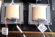
My semi-finished VT60.
Output and mains transformer.
OPT1
6.5k Raa
A1 114.16 Ohm
A2 114.45 Ohm
More in the picture
OPT2
6.5k Raa
A1 114.2 Ohm
A2 112 Ohm
More in the picture
Pipes SOVTEK 6550
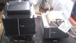
MAINS
300 VA electrically dimensioned at the bottom!
My semi-finished VT60.
Output and mains transformer.
OPT1
6.5k Raa
A1 114.16 Ohm
A2 114.45 Ohm
More in the picture
OPT2
6.5k Raa
A1 114.2 Ohm
A2 112 Ohm
More in the picture
Pipes SOVTEK 6550
MAINS
300 VA electrically dimensioned at the bottom!
Attachments

looks like the OPT is toast, replaced bias resistors, left out output valves and powered it up. Blew the fuse pretty much straight away. Disconnected B+ from suspect OPT and it was ok. Checking voltages B + looks very high ( 470 v ). I'm thinking the mains tranny might well be a 220 v unit...
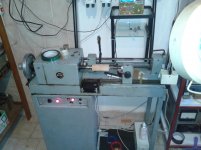
Yes, i make the transformers.apmme
did you make your own Transformers
Good to do for myself - a hobby. 🙂
Attachments
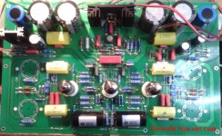
One thing I see is -40v bias for 6550 on schematic. That's a lot of current! I would expect about -50v. The 6550 is meant to have max 47K series bias however 100k is often used. I think they will have gone into thermal runway. There's no current limit on the HT. I think I would put a fusible resistor in for R18 to save your OPT.
Last edited:
As a follow up I have not powered it back up to test voltages since I'm waiting for some inline fuses I ordered, however i can give you the following information:
The DC resistances ( another meter ) are as follows on primary of suspect OPT-
Plate1/B - 42.3 ohm
G1/B 13.6
G2/B 12.3
P2/B 67.5
Nothing to earth
Other side reads respectively:
77.2
34.2
32.8
86.2
I fitted KT88's ( matched pairs ). The same screen resistor on V5 had gone ( different tubes ). Also V4 on the other channel had burnt out. The suspect transformer is the V5/V7 side.
One thing I see is -40v bias for 6550 on schematic. That's a lot of current! I would expect about -50v. The 6550 is meant to have max 47K series bias however 100k is often used. I think they will have gone into thermal runway. There's no current limit on the HT. I think I would put a fusible resistor in for R18 to save your OPT.
I think that ship has sailed - it's over and out for that tranny.
Sorry got lost on the thread and missed Mr Summer's good comments. If you do get it working again don't run them at that current. I usually go for 35-40ma per tube.
If you put inline fuses straight from the HT to the output transformer put a reverse biased diode to ground. That way it will catch the current in the output transformer or you will end up with 4kv across the fuse if it blows.
A lot of amps do use 100k bias. If you drop to 47k you may run out of drive I don't know and the coupling caps need to get bigger.
Hopefully your ship has not sailed.
Last edited:
Thanks for your input, I really appreciate it. Unless i can get another output transformer its a good boat anchor. ARC mentioned a figure to have one made that is laughable..Sorry got lost on the thread and missed Mr Summer's good comments. If you do get it working again don't run them at that current. I usually go for 35-40ma per tube.
If you put inline fuses straight from the HT to the output transformer put a reverse biased diode to ground. That way it will catch the current in the output transformer or you will end up with 4kv across the fuse if it blows.
A lot of amps do use 100k bias. If you drop to 47k you may run out of drive I don't know and the coupling caps need to get bigger.
Hopefully your ship has not sailed.
Sorry got lost
<snip>
blows.
A lot of amps do use 100k bias. If you drop to 47k you may run out of drive I don't know and the coupling caps need to get bigger.
Hopefully your ship has not sailed.
Larger then 50k gridresistors with 6550 and fixed bias is outside spec.
Violating specefications is never a good idea.
If by any reason 100k is wanted, KT88 will be within spec.
- Home
- Amplifiers
- Tubes / Valves
- ARC VT60