I don't have much experience of MOSFETs or any silicon components really, but I stumbled across this which looks useful.
ASSR-4118-003E BROADCOM LIMITED, MOSFET Relay, 400 V, 100 mA, 35 ohm, SPST-NO | Farnell element14
It takes a 3mA current on the input to light up an LED which then switches on a power rail up to 400V.
Anyone used this or similar ?
ASSR-4118-003E BROADCOM LIMITED, MOSFET Relay, 400 V, 100 mA, 35 ohm, SPST-NO | Farnell element14
It takes a 3mA current on the input to light up an LED which then switches on a power rail up to 400V.
Anyone used this or similar ?
Anyone help me with using this component please ?
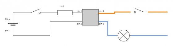
I don't have any experience with using solid state components, so I rigged up a brief test circuit (attached). My expectation was that the bulb would only light with the battery in circuit. Actually the bulb is on whether the battery is connected or not and it is clearly flickering. Just to check, I reversed the battery terminals but to no effect.
Datasheet here : http://www.farnell.com/datasheets/2...44.750499269.1504101584-1124664154.1501012602
I'd appreciate any pointers.
Attachments

Last edited:
I've used discrete versions of these. The bulb should not light when the LED is inactive. What is the applied bulb voltage and is it AC or DC ?
You could try a simple LED/Resistor/Battery arrangement on the bulb side as a test.
You could try a simple LED/Resistor/Battery arrangement on the bulb side as a test.
I don't have any experience with using solid state components, so I rigged up a brief test circuit (attached). My expectation was that the bulb would only light with the battery in circuit. Actually the bulb is on whether the battery is connected or not and it is clearly flickering. Just to check, I reversed the battery terminals but to no effect.
Datasheet here : http://www.farnell.com/datasheets/2...44.750499269.1504101584-1124664154.1501012602
I'd appreciate any pointers.
Be aware of the mosfets off capacitance, especially if it's a low power bulb, like a LED one.... Seems to be missing from the datasheet, but probably some hundred pf....
I have a outdoor lamp with a LED bulb which flicker once in a while when off, the capacitance in the regular switch is enough....
Or you could have a defect mosfet relay, mosfets often short when defect, test it with a multimeter....
This also happen when the switch has a neon inside. The easier solution is to place a 1µF 400V in the lamp socket. It gave me good results.
I've used discrete versions of these. The bulb should not light when the LED is inactive. What is the applied bulb voltage and is it AC or DC ?
You could try a simple LED/Resistor/Battery arrangement on the bulb side as a test.
UK mains, 240VAC. I'm not used to reading these datasheets, it could easily be me misunderstanding it - it's possible that only the 4119 is both AC and DC capable. I'll try the battery/resistor/LED on the output for the test as suggested thanks.
Once I've proven that it works as expected I plan to use this to switch on a filtered 250VDC supply once a 100VDC bias circuit is up (for a fixed bias tube amp).
According to the datasheet its rated for max output voltage 400V, with a max output current of 100mA. However it also says max output power dissipation of 300mW. Input-Output capacitance is 0.4pF.
240 volt mains is nominally 340 volts peak and so 400 volt is a fairly standard rating for mains capable parts. The switches (4118 and 4119) are definitely AC and DC capable. The 4119 brings out an extra connection for DC only operation and allows the FET's to run in parallel... which you can't do for AC use.
Try one with a low voltage battery supply feeding an LED first and confirm it all works as expected and with the polarity either way around.
Try one with a low voltage battery supply feeding an LED first and confirm it all works as expected and with the polarity either way around.
Set up a test circuit with battery/resistor/led on both input and output. Each lights when I close the individual circuits with no switch involved. Ready to test the optocoupler.
If only I could solder wires to the damned legs now... Lol. Is there a bigger version of these that's easier to work with? I'm not using PCB, but point to point wiring
If only I could solder wires to the damned legs now... Lol. Is there a bigger version of these that's easier to work with? I'm not using PCB, but point to point wiring
Last edited:
In the off-state, with 240VAC, the optomos switch is operating pretty close to max rated withstand voltage - too close imho.
What is your 'load' that you want to connect? You will need to be cautious of peak current, and power dissipation given the small case (the 300mW rating may be for the device pads and pcb providing some heatsinking) and that Rds-on could be quite high due to junction temp.
Perhaps aim for 5mA drive
What is your 'load' that you want to connect? You will need to be cautious of peak current, and power dissipation given the small case (the 300mW rating may be for the device pads and pcb providing some heatsinking) and that Rds-on could be quite high due to junction temp.
Perhaps aim for 5mA drive
Last edited:
In the off-state, with 240VAC, the optomos switch is operating pretty close to max rated withstand voltage - too close imho.
You would think so and yet 400v is a common commercial rating on such devices intended for 240 vac operation. Thyristors, triacs, all would typically be 400 volt parts for this market.
You would think so and yet 400v is a common commercial rating on such devices intended for 240 vac operation. Thyristors, triacs, all would typically be 400 volt parts for this market.
My concern would be related to the ruggedness of the die in the device to any transient over-voltage, whether from the mains side, or as a result of inductance in the load circuit. The larger the die, the likely better the survivability.
Can't disagree on that, I'm just saying what is commonly used in the commercial arena 🙂 A good design would include transient suppression to limit any such spikes and associated fast voltage rise times.
If higher voltage alternatives are available and they are cost effective then it makes sense to use them.
If higher voltage alternatives are available and they are cost effective then it makes sense to use them.
I can see 600V devices in Farnell. Whereas I don't recall seeing much above 400V a decade or so ago, and used AQW214 then as it was a practical cost-effective device for automated ranging in battery monitor systems.
You would think so and yet 400v is a common commercial rating on such devices intended for 240 vac operation. Thyristors, triacs, all would typically be 400 volt parts for this market.
I'm no device physicist, but I could imagine that a triac simply switches on when it is subjected to an overvoltage peak. That is, your lamp will then flicker, but nothing will get damaged. I'm not sure what would happen to a high-voltage MOSFET.
What kind of bulb did you use? These devices are signal switches (i.e. low current), and they don't like to be overloaded, no matter how briefly. The part has no rating for surge current, so if you tried to switch an incandescent lamp, chances are very high that you blew it up because of the bulb's inrush current.
A little background: these "relays" are in fact two anti-series connected mosfets (sources connected together) which receive gate drive voltage from a series string of diodes. This series string of diodes operates in photovoltaic mode (yes, like a mini solar panel) to generate gate drive voltage when the built-in LED is lit. The LED shines through a light conductor onto the PV diode string, this light conductor allows the LED to be placed far enough away from the switched circuit to achieve the desired insulation.
A MOSFET is only turned fully turned on up to a certain current at a given drive voltage, above this current it "lets go" and becomes a current source. In this mode, dissipation (and thus heat production) shoots up and the device is easily damaged. So if you want to switch a load with a MOSFET, and it's not turned on hard enough for the highest current that occurs, it will blow up due to excessive dissipation.
The PV diode string in the "relay" is long enough to drive the MOSFET to turn on up to its rated current, but not any longer, because that would increase the LED drive requirements, the device's size and cost. That's a catch when using these devices.
I was very worried about the size of it, both for physical connections and for it's ability to handle the load, which will be 250vdc @ approx 65mA. Under low load that will likely rise to 350 to 400v (bleeder both before and after the switch). It's purpose is to only allow b+ when the bias voltage is present, both for failure protection and to delay startup. I'm currently using a coil relay to switch the heaters off the rectifiers, which works well but I can't help wondering about noise feed back through the inducting coil to the bias circuit.
I looked for another device, both for higher current handling during startup and in a better format (longer legs).
I looked for another device, both for higher current handling during startup and in a better format (longer legs).
Last edited:
I think you are saying that the optomos switches a 240VAC relay coil to a 240VAC supply, and the relay coil has a 65mArms steady-state operating current (from a datasheet)?
If that is the case then the steady-state current likely has a continuous peak level approaching 100mA. And turn-on is likely to include a significantly higher peak current, limited by the coil DCR - and apparently the turn-on peak could be circa 2-3x steady-state.
If that is the case then the steady-state current likely has a continuous peak level approaching 100mA. And turn-on is likely to include a significantly higher peak current, limited by the coil DCR - and apparently the turn-on peak could be circa 2-3x steady-state.
I read something a but different in RyhthMick's description. As I see it, he only wants his amp to turn HV on when the bias is present, so he wishes to use the "relay" to switch the B+ on once there is bias.
If you want to go for that, a better solution would be to use a photovoltaic optocoupler, and an external MOSFET which is beefy enough to handle the load and surge. It is basically the same part, but without the built-in switch MOSFET.
If you want to go for that, a better solution would be to use a photovoltaic optocoupler, and an external MOSFET which is beefy enough to handle the load and surge. It is basically the same part, but without the built-in switch MOSFET.
- Home
- Amplifiers
- Power Supplies
- Anyone used this "optical MOSFET relay" ?