Im working on a project that will require at least 12 avail pins at high(over 500v) isolation
i don't mind getting a connector with more pins and grouping them together to increase current handling
but heres a map of what i presently have in mind
All values are DC
1= 500v 300 mA
2= 300v 300 mA
3= 300v 25 mA
4= 12.6v 10 A peak less steady
5= 12.6v return
6= 6.3v 10 A peak less steady
7= 6.3v return
8= -67 to -113v negligible current
9= ground
10= ground
11= ground
12= ground
i spotted these but is there anything better/closer to states side? russia tends to take potentially months to get packages from
24 pin USSR connector Male + Female Complete Lot of 2 | eBay
I've used the Cinch Jones style of connectors with sucess. They come in-line or chassis mount, and some have metal pieces on the sides to lock them together. You'll have to keep searching for the correct configuration for your application.
Cinch Jones P412-CCT S412-DB Connector Set | eBay
Cinch Jones P412-CCT S412-DB Connector Set | eBay
cinch's jones series seems to cite 250v AC max for there plugs so i think i'd be afraid of flashover
perhaps instead of one plug a couple plugs are in order. or just eat the shipping time from moscow
perhaps instead of one plug a couple plugs are in order. or just eat the shipping time from moscow
Hello ryuji, off the top of my head, I can think of these connectors:
Lapp Epic connectors
Weidmuller Rockstar connectors
Harting Han eV series connectors
I'm sure there are many others, probably cheaper than the ones listed above, but this gives you an idea of what's out there. Try doing a search on Newark, digikey, Allied, Mouser, etc. websites and see what you find. I think you will be overwhelmed very quickly!😱😉
Peace,
Dave
Last edited:
The plastic CPC connectors are pretty cheap and easy to work with. Its probably not the "approved" method but you could always use a connector with pins you install yourself and leave empty spaces around the high voltage ones.
If you want the metal military style connectors look at DDK.
DMS SERIES | DDK | Connectors | Circular Connectors | Product Catalog Search Results | Galco Industrial Electronics
If you want the metal military style connectors look at DDK.
DMS SERIES | DDK | Connectors | Circular Connectors | Product Catalog Search Results | Galco Industrial Electronics
250 volts is conservative 'cause I've used them higher. If you bought a set with more pins then needed, you could remove some next to the HV pins. Consider the plain black bakelite tube sockets that had 500 volts on them and lasted for decades.
i don't mind getting a connector with more pins and grouping them together to increase current handling
Not a good idea unless you can split the loads into separate circuits. Contacts in parallel don't share current equally.
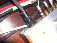
+1 on the Amp CPC series. The series 1 CPC connectors are rated for 600V (AC or DC) and 13 amps. Affordable, and easy to use. I'm using a 9 pin on my Tubelab SE running up to 400V B+ with all of the pins used. Been using it for months without issues. They have a variety of shell sizes, std and reverse sex, gold contacts, etc.
Attachments
+2 on the CPC series. I've used these between amps and remote power supplies with great success. At first I thought there should be no problem running parallel wires for more current, but I can see that if one connection started to go high resistance the situation is unstable and soon you might have a single wire handling all the current. Still, if the current was within the limits of a single line, paralleling should lower resistance and work reasonably well. I wouldn't do it if the total current exceeded the limits for one line.
cinch's jones series seems to cite 250v AC max for there plugs so i think i'd be afraid of flashover
I built my 845SE using a Cinch Jones connector on the umbilical between the amp and power supply. The connector carries the HV which is 1100 volts at 200+ mA DC, the driver B+ which is 500 volts and all the filament and low voltages. The amp has been in south Florida humidity for 5+ years with no issue. The pins adjacent to the HV pin are not used.
aha, so there 250v rating is quite modest if you take care to isolate adjacent pins. then thats indeed a optionI built my 845SE using a Cinch Jones connector on the umbilical between the amp and power supply. The connector carries the HV which is 1100 volts at 200+ mA DC, the driver B+ which is 500 volts and all the filament and low voltages. The amp has been in south Florida humidity for 5+ years with no issue. The pins adjacent to the HV pin are not used.
I thought I said that in not so many words. One possible problem I can see is that George and I were probably using old stock Jones connectors that were made in the U.S. If they're now being made in China, God only knows what quality they are. Try to find NOS!aha, so there 250v rating is quite modest if you take care to isolate adjacent pins. then thats indeed a option
Just before home time at work so was browsing.
As it happens I have the 3" thick MIL-SPEC MIL-C-5015, MIL-C-26482, MIL-C-83723 etc. Connector "Encyclopeadea" open in front of me on the desk from the real work I was doing a little earlier.
Depending on Shell Size, Pin Size and number of pins these things are rated to 4200V DC and 3000V AC.
For us DIY'ers without access to the special crimp tools etc. we are pretty much restricted to the solder style connectors, that is
MS3106 series cable mount straight plug/socket
MS3102 series box mount recepticle.
These often come up at disposal/clearance sales and similar since people who use them every day now prefer the crimp style versions.
REMEMBER - Safety:
Always use a female (socket) at the power supply so there are no exposed pins with "hot" voltages on them.
Use a male plug to plug into that.
If using connectors both ends of the connecting cable then you want a male socket at the amp end and a female cable connector to plug into that.
That way there are never any exposed pins with voltages on them regardless of which end you unplug first (of-course it would have been smarter if they turned it OFF first). For DIY thats just good sense. In the day job I its one of the things I insist on and check when doing design reviews for other engineers.
If anyone needs info on these MS Connectors you manage to acquire you can send me a PM and I can look up voltage and current ratings for what you have.
Cheers,
Ian
One possible problem I can see is that George and I were probably using old stock Jones connectors that were made in the U.S.
I never thought about this, but yes, my connectors are at least 50 years old!
- Status
- Not open for further replies.
- Home
- Design & Build
- Parts
- anyone know of a source for 12 pin+ connectors?