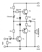
This is a very simple amplifier. I think too simple, and what appears to be labeled as 100 Ohms is the feedback and bias resistor that should be at least 100K Ohms. The large output transistors and "2.2 Ohm" emitter resistors make a 3 Watt amplifier out of parts suitable for 50 Watts, so maybe the idea is that it will be idiot proof? I would draw it out for you but I'm sure anyone who knows a bit of electronics can reverse engineer this is a few minutes.

The two power transistors are the output stage. The 2.2 Ω resistors are the emitter resistors. The BC547 is the VAS. The two diodes bias the output stage, though not very well. It'll be operating in Class B.
So now use this information to draw a Class B bipolar output stage with an NPN VAS. Connect the dots using the information you already have.
Based on the 12 V DC power supply I'm guessing this is a headphone amp.
Tom
So now use this information to draw a Class B bipolar output stage with an NPN VAS. Connect the dots using the information you already have.
Based on the 12 V DC power supply I'm guessing this is a headphone amp.
Tom
I love such circuits: very very simple, pure, endless clean and dynamic and musical. Beats EVERY complex pp-amp - experiences in speakers and sources and so on provided!
The 1 kOhm and the 100 kOhm (correction reminded by tomcr, see below) resistors place by trimmers.
Emitter resistors you could select down to 1 Ohm or 0,47 Ohm. Just decide per listening - connected to the speakers to be driven.
2SB817 and 2SD1047 sound very very ugly! Do use any TO-220 or, still better, TO-126.
Use any vehicle battery.
Disadvantages:
Complementary transistors sound differently, and
the positive half-wave is modulated by two other components: the two diodes for biasing.
Could be, oscillation will occur. Simply insert a Zobel, Boucherot element at the output.
Advantage: A component selection by listening is not complicated and would increase the sound enormously.
Have much much fun!
Last edited:
The resistor to the base of the BC547 should be 100 kΩ. Not 100 Ω as shown in the schematic.
I'd be careful about tweaking the emitter resistors too much. The bias spreader (the two diodes) aren't thermally connected to the output stage, so they won't provide any protection against thermal runaway. You increase the odds of thermal runaway with lower emitter resistors. This isn't a high-powered amp anyway, so 2.2 Ω is just fine.
Tom
There is such a thing as “too simple” and this is it. The odds of it working are only about 50/50 depending on which parts you choose, and only 5% or less of it working properly (ie, getting a halfway symmetrical sine wave out of it, and enough bias not to sound totally gross). Band aiding it by making all the resistors trim pots is just that - a band aid.
Three resistors, a pot and two caps could turn it into something that would work pretty much every time. But it’s not as ‘simple’ anymore, and could still be outperformed by an old TDA2002.
Three resistors, a pot and two caps could turn it into something that would work pretty much every time. But it’s not as ‘simple’ anymore, and could still be outperformed by an old TDA2002.
True. But that shouldn't exclude it as a learning platform. The LM386 would outperform this circuit as well.There is such a thing as “too simple” and this is it. [...] But it’s not as ‘simple’ anymore, and could still be outperformed by an old TDA2002.
Tom
A 1A "learning platform": e.g. the sonic difference with or without bootstrap ("boost"). What does the ear do? Is a "halfway symmetric sinuswave" or the lack of further parts (and further noise?) audible or even sound-decisive?
IMO, it skips a few critical steps. One should learn how to force the voltage at the collector to something resembling half the supply before adding the power followers. If you don’t, then you fight asymmetrical voltage swing (or worse, being stuck to the rail if you put in a really high beta part) at the same time as fighting the consequences of severe under or over bias.True. But that shouldn't exclude it as a learning platform. The LM386 would outperform this circuit as well.
Tom
No. A learning platform in the sense of: Build it, measure the DC operating points, look at the distortion, etc. Or set it up in a circuit simulator and do the same. Or ... hey! ... grab a textbook like Sedra/Smith Microelectronic Circuits and analyze the circuit. Learn stuff.A 1A "learning platform": e.g. the sonic difference with or without bootstrap ("boost"). What does the ear do?
Tom
Oh, I wholeheartedly agree. It runs deep in Class B with the Darlington devices being biased by only two diode drops. It has very low loop gain. Maybe a few hundred at DC on a good day, so it'll have significant distortion. And, as you point out, the DC operating point could be optimized for better use of the available rail voltage. All this is something one could learn by dinking around with the circuit either in the lab, in a circuit simulator, or on paper with a calculator, hence, my suggestion of it as a learning platform.IMO, it skips a few critical steps.
Tom
I expand: a learning platform not only for amplification of low complex signals for elevators, mowers and so on as, obviously, the most do, but also for amplification of high complex "music-signals"-)No. A learning platform in the sense of: Build it, measure the DC operating points, look at the distortion, etc. Or set it up in a circuit simulator and do the same. Or ... hey! ... grab a textbook like Sedra/Smith Microelectronic Circuits and analyze the circuit. Learn stuff.
Tom
And, also, everlasting: What does the ear do;-?
diy-AUDIO. Audire: to listen, to hear;-)
you mean dsp, right ?I expand: a learning platform not only for amplification of low complex signals for elevators, mowers and so on as, obviously, the most do, but also for amplification of high complex "music-signals"-)
And, also, everlasting: What does the ear do;-?
diy-AUDIO. Audire: to listen, to hear;-)
;-)
dsp: digital signal processor;-?
I don't know of any in whose development, for example, current have been taken into account. Much much to do every time to get a clean sound;-)
dsp: digital signal processor;-?
I don't know of any in whose development, for example, current have been taken into account. Much much to do every time to get a clean sound;-)
I agree , too simple.
Just a few more parts equals something rock solid that will easily outlast the speaker.
That 2sd1047/2sb817 could REALLY sound good with a good design. (this circuit would be real happy with them).
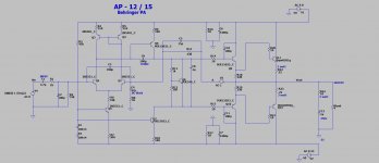
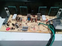
The Behringer below lasted 20 years - just needed new caps. You could build it without C11/10/5 and with any junkbox semi's.
It would actually be "audiophile" at normal listening levels. A "Cute" little 50W amp. BTW , it's a real amp ... I run both my subs with them.
As a "learning platform" ... Q5/7 current source , Q3/4 mirror , etc .... I've built this on my hobby board in 5 min. Works nice.
OS
PS - Q8/11/12 go on any heatsink (junkbox ??)
Just a few more parts equals something rock solid that will easily outlast the speaker.
That 2sd1047/2sb817 could REALLY sound good with a good design. (this circuit would be real happy with them).
The Behringer below lasted 20 years - just needed new caps. You could build it without C11/10/5 and with any junkbox semi's.
It would actually be "audiophile" at normal listening levels. A "Cute" little 50W amp. BTW , it's a real amp ... I run both my subs with them.
As a "learning platform" ... Q5/7 current source , Q3/4 mirror , etc .... I've built this on my hobby board in 5 min. Works nice.
OS
PS - Q8/11/12 go on any heatsink (junkbox ??)
Attachments
Last edited:
- Home
- Amplifiers
- Solid State
- anyone have schema version of this?