Well the first thing you will say is:"You haven't searched the forum!!!"
Well I did!And I did see the Rane Mixers but I haven't foud this schematic anywhere....
So pls if anybody Knows tell me
Well I did!And I did see the Rane Mixers but I haven't foud this schematic anywhere....
So pls if anybody Knows tell me
Could you start with this?
http://www.djzone.net/pg/0101/tt01001.shtml
http://www.cs.washington.edu/homes/sauravc/digital_xfader/djcross.pdf
Here is a rane mixer with schematic.
http://www.rane.com/pdf/old/mp24sch.pdf
/Hugo 🙂
http://www.djzone.net/pg/0101/tt01001.shtml
http://www.cs.washington.edu/homes/sauravc/digital_xfader/djcross.pdf
Here is a rane mixer with schematic.
http://www.rane.com/pdf/old/mp24sch.pdf
/Hugo 🙂
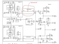
Ok thanks a lot.I really helped me.Now I got only one stupid question left.What do u think this schematic mean?.I need to know how the signal fron the crossfader section goes to the master output.Is that o wire a shortcut of some sort or it is something else?
I thinck it is.Do U ?
I thinck it is.Do U ?
Attachments
 !!!!!!!!!!
Red, don't worry about the spelling. We understand you!! 🙂
To me it's a wire, but its a bit strange that the headphone pcb only consists of one wire.
Do you have a more detailed schematic of that headphone pcb?
/Hugo
To me it's a wire, but its a bit strange that the headphone pcb only consists of one wire.
Do you have a more detailed schematic of that headphone pcb?
/Hugo
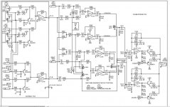
OK You're right .Maybe i should post all the schematic.It's Rane Mp22 schematic.it's a pdf.Take a look at it fi u can and then tell me what do u think of it.I'm intrested in the crossfader seciton and how to hook it up to the rest of the mixer.That headphone pcb look something like this(see the picture below) and the link to the rane pdf file is:
http://www.rane.com/pdf/old/mp22sch.pdf
http://www.rane.com/pdf/old/mp22sch.pdf
Attachments
Red
All the connections in the PDF marked with "J" are connections.
Looking for example at the headphone PCB layout on page 2 you can see J37, J17, J18, J20, J42, J32.
The first pin is always labeled 1 so you know from where to start counting.
In the schematic you see for example the wire you showed in post #3 goes from connector 37-8 to connector 18-1 on the headphone pcb.
I can't tell you anything about the quality of those mixers; I never heard one.
/Hugo 🙂
- Status
- Not open for further replies.
- Home
- Source & Line
- Analogue Source
- Anybody Knows anything about Crossfaders?