My conundrum involves a PXm900 (totally different beast to PM900). The power supply splits via fuses to the two power amp sections, but these are tied back together again via the heatsinks. There is no evidence of there ever having been any insulation between the output device collectors and the heatsinks (this is conventional topology, not QSC style grounded collector). Why have fuses in parallel ???. The upshot of this is the failure of a crowbar thyristor caused all 4 fuses and both channels to fail.
Ideas????
Cheers
M
Ideas????
Cheers
M
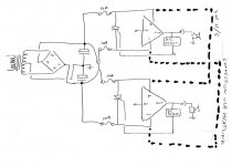
Attachments
My conundrum involves a PXm900 (totally different beast to PM900). The power supply splits via fuses to the two power amp sections, but these are tied back together again via the heatsinks. There is no evidence of there ever having been any insulation between the output device collectors and the heatsinks (this is conventional topology, not QSC style grounded collector). Why have fuses in parallel ???. The upshot of this is the failure of a crowbar thyristor caused all 4 fuses and both channels to fail.
Ideas????
Cheers
M
You're right -- boy oh boy 😱...for Bob Carver that is a bit crude I am guessing that the mains inlet fuse at the primary of transformer would be about 6.3A ish. any one of those crowbars join Pos and Neg rail together is going to momentarily make the transformer jump out of it's skin - causing a massive inductive transfer through the transformer and what primary inlet fuse it has is going to go as well - taking all power out of the system common to both amplifiers anyhow.
I dont like that design at all - that's not elegant or wise.
What is more typical of Mr. Carver is to look at a design and overcomplicate the thing until what could be achieve equally as well with 10 discrete components, is stuffed with op-amps and 300 supporting devices.😉
- Status
- Not open for further replies.