Hi.
Got a Sony DE375.
It is not powering on. Actually it doesn't do anything.
I took it appart and the Standby board is not forwarding any voltage to Display Board. So I think this is the case here.
Have a look at the service manual. The scheme is on the 17th page.
http://sportsbil.com/sony/STR/STR-D/STR-DE375_v1.0.pdf
The relay is working If external 9V is applied.
The Standby board transformer is working and putting out voltage. I get a voltage reading unitl the Q951 on the Stand by board. That 6.2V on the Base is missing, its more like 1.8V in my case.
I think the 5.6V regulator is down. But what could I replace it with?
Its a 2SD1513 but its not available from any store here.
Can I use a 7805 ?
I have disconnected cables from this board while measuring.
Any ideas?
Its a 2SD1513 but its not available from any store here.
Can I use a 7805 ?
You can't replace a transistor with a regulator - different pins!
Do you get 9.5 V on the collector?
If not, something is wrong with the corresponding transformer secondary or the rectifiers after it. The 9.5 V come straight from the transformer.
If yes, check R950.
If you have 1.8v on the base you will not see 5.6 on the output. You should be seeing around 0.7 to 0.8 across the base emitter junction in this state. Do you ? The transistor may or may not be faulty.
Just jumping in here... C950 would be a typical problem area. Unless you scope check the rails don't assume they are clean and correct.
Although the transistor is quite high gain I would think most medium power NPN such as a BD131 or TIP41 should be suitable. It may well be OK though.
Just jumping in here... C950 would be a typical problem area. Unless you scope check the rails don't assume they are clean and correct.
Although the transistor is quite high gain I would think most medium power NPN such as a BD131 or TIP41 should be suitable. It may well be OK though.
Hi.
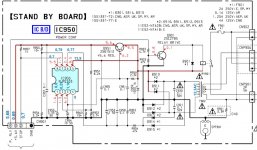
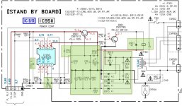
All the RED values are from the service manual. I didn't delete them to have a clear reference.
I have added the Blue numbers from the values I measured.
All the RED values are from the service manual. I didn't delete them to have a clear reference.
I have added the Blue numbers from the values I measured.
Yes, I realise that 🙂 Although you measure 13.9 volts instead of around 9 volts that can't be taken as a guarantee that all is well and its high just because its unloaded. If there were excess ripple on the rail then a DVM reading is useless.
Also check R950, make sure its not gone open.
Also check R950, make sure its not gone open.
Measured resistors and changed some capacitors and diodes on the board.
Everything marked green is checked.
Everything marked green is checked.
Attachments
Last edited:
I can't offer a quick fix for this. If the passive parts are OK and the reservoir cap OK (it probably is OK but I would want it proved so) then unless you are 100% confident in checking the series pass transistor and interpreting the results I think you have to swap it out.
The IC isn't a regulator as such, its a reset generator that monitors the rail/s, although it does offer the facility to generate a user programmable output voltage. Only when all other possibilities are proved OK would I suspect the IC.
The IC isn't a regulator as such, its a reset generator that monitors the rail/s, although it does offer the facility to generate a user programmable output voltage. Only when all other possibilities are proved OK would I suspect the IC.
You mean the Q951?
I can build a test fixture for it.
Just one question though.
If the power rail +5.6V is unloaded will the Q951 still work?
Maybe there is something wrong on the Screen PCB and the voltages will never be right if the Standbyboard is disconnected from it or has a wrong load on it.
I can build a test fixture for it.
Just one question though.
If the power rail +5.6V is unloaded will the Q951 still work?
Maybe there is something wrong on the Screen PCB and the voltages will never be right if the Standbyboard is disconnected from it or has a wrong load on it.
That's a good question. Yes, I think it should all work as a standalone because there are no 'inputs' to the chip to override anything.
Hi.
So the transistor was good.
Can I run the amp without the standby board?
What would be the end result?
I assume that it might just blow up the PA if there is something wrong with it.
But I am sure its fine..
I already run the 5.6V from external PSU.
Stop pin was high 5.3V.
Relay pin got around 5V back but didn't switch.
So I assume that it should have turned the Relay high.
I can see a voltage change on the realy if I press the Power button.
But its a very small change in voltage. I would really like to hard-start the unit.
I was just looking at your diagram and voltages again.
Q901, the relay driver. Do you have 5 volts on the top end of R903 when you try and turn it on ? I notice you marked that line as 5.68 volts. If you do have 5 volts present on that line and the relay isn't firing then Q901 is faulty.
Q901, the relay driver. Do you have 5 volts on the top end of R903 when you try and turn it on ? I notice you marked that line as 5.68 volts. If you do have 5 volts present on that line and the relay isn't firing then Q901 is faulty.
- Status
- Not open for further replies.
- Home
- Amplifiers
- Solid State
- Another Sony DE375 Broken (2SD1513 no voltage)