Hello,
First of all, sorry for another Grounding question. I've searched different topics already but for me the best solution of grounding is still unclear.
But lets start at the beginning. I'm currently trying to build my first partially self designed preamplifier. Therefore I'm having 5 Pairs of inputs with XLR and RCA each. Those XLR Inputs get converted to single ended by using Douglas Selfs circuit. Those single ended inputs then get switched by DPDT Relays and one Pair of single ended inputs is connected to my actual Preamplifier (attenuator first).
So now about my uncertainty: I've read so much and there are so many people arguing about the best way of switching inputs and connecting Grounds that I'm completly lost about which way might work for me.
For clarification I've created some drawings with the possibilities I've found, which is attached to the end of my post.
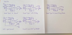
On the top left drawing the unused Inputs gets shorted to Ground which should prevent crosstalk/noise.
On the top middle drawing the unused Input hot signal is left floating, while on the top right drawing the unused input gets shunted to Ground through a resistor, also to prevent crosstalk/noise or prevent the connected cabel from acting as an antenna. In the bottom right/middle drawing the Input grounds are connected to something like a star point through a resistor, while in the bottom left drawing the Grounds are switched too by a DPDT relay to prevent Ground loops.
So could anyone tell me which way of switching the inputs and connecting the grounds I should use and why it is better than the others?
Thanks in advance and with best regards
DosenZorn
Edit: corrected some mistakes
First of all, sorry for another Grounding question. I've searched different topics already but for me the best solution of grounding is still unclear.
But lets start at the beginning. I'm currently trying to build my first partially self designed preamplifier. Therefore I'm having 5 Pairs of inputs with XLR and RCA each. Those XLR Inputs get converted to single ended by using Douglas Selfs circuit. Those single ended inputs then get switched by DPDT Relays and one Pair of single ended inputs is connected to my actual Preamplifier (attenuator first).
So now about my uncertainty: I've read so much and there are so many people arguing about the best way of switching inputs and connecting Grounds that I'm completly lost about which way might work for me.
For clarification I've created some drawings with the possibilities I've found, which is attached to the end of my post.
On the top left drawing the unused Inputs gets shorted to Ground which should prevent crosstalk/noise.
On the top middle drawing the unused Input hot signal is left floating, while on the top right drawing the unused input gets shunted to Ground through a resistor, also to prevent crosstalk/noise or prevent the connected cabel from acting as an antenna. In the bottom right/middle drawing the Input grounds are connected to something like a star point through a resistor, while in the bottom left drawing the Grounds are switched too by a DPDT relay to prevent Ground loops.
So could anyone tell me which way of switching the inputs and connecting the grounds I should use and why it is better than the others?
Thanks in advance and with best regards
DosenZorn
Edit: corrected some mistakes
Attachments
Last edited:
I've also got some other questions regarding different Ground connections. I'm using an unregulated +12VDC supply for the Relay coils, a regulated +24VDC supply for the preamplifier circuit, regulated +-15VDC supply for the OPAs drawn in those pictures, as well as a regulated +5VDC supply for the digital control logic. Since the unregulated relay supply and the digital supply may degrade the audio signal ground, should I leave those grounds disconnected from the signal ground? Do I connect them to the chassis/earth? Should I connect them by using a resistor?
Also on digital circuit boards its common practice to have a ground layer but I've never seen one on Papas B1K or Aleph Boards. Is there a reason why one shouldn't use a groundlayer on audio applications?
I'm sorry for all these questions, but I'm so confused right now and hopefully someone might enlighten me.
Make sure that the OPamps can be shorted to ground.
A resistor at OPamp output wouldn't accomplish what you are thinking
I personally have great success with ground planes on each ground
Join the ground planes at earth ground point
Have used both resistors and no resistor at earth with no difference
The idea behind using resistors is to channel the ground path to reduce loop interference.
If it can be done without, then this is the way to go.
If you experience some noise, then resistors may help.
At first thanks for your answer. Do you have a recommendation for the hot wire switching too?
Should I either leave unused inputs (signal wire) floating or short/shunt them to ground?
Should I either leave unused inputs (signal wire) floating or short/shunt them to ground?
Make sure that the OPamps can be shorted to ground.
So my plan is using the OPA2134 Opamps. The data sheet says "output short circuit: continuous". I suppose this means I'm able to use them without damaging them when shorted right?
Attachments
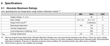
Practically all opamps are designed to survive a short-term output short - however its very bad practice to short any output - in fact if you short an opamp you increase the signal currents and make them square waves, probably making crosstalk via induction much worse.
If you have a problem with offness(*) in a switch there are much better ways to do it, like ensuring low impedances at the receiving side.
(*) offness relates to the fact a switch in the off position doesn't have infinite impedance due to the inter-contact capacitance. Sometimes poor off-ness is due to faulty ground layout (not using star-grounding), and is nothing to do with the switch.
I've also got some other questions regarding different Ground connections. I'm using an unregulated +12VDC supply for the Relay coils, a regulated +24VDC supply for the preamplifier circuit, regulated +-15VDC supply for the OPAs drawn in those pictures, as well as a regulated +5VDC supply for the digital control logic. Since the unregulated relay supply and the digital supply may degrade the audio signal ground, should I leave those grounds disconnected from the signal ground? Do I connect them to the chassis/earth? Should I connect them by using a resistor?
Also on digital circuit boards its common practice to have a ground layer but I've never seen one on Papas B1K or Aleph Boards. Is there a reason why one shouldn't use a groundlayer on audio applications?
I'm sorry for all these questions, but I'm so confused right now and hopefully someone might enlighten me.
Relay and logic grounds should be kept separate from the audio ground.
IF the audio circuitry uses the same power transformer windings as the relay and logic circuitry, then the relay/logic ground and audio ground should be connected at only ONE point. That point should be by the main power supply capacitors. If you have a separate power supply board, then you must run two grounds to the audio/logic board.
Also when using the same power transformer windings, you must use separate diodes and smoothing capacitors for the relay/logic and audio power supplies. Do not give noise from the relay/logic section any opportunity to inject noise into the audio circuitry.
Logic grounding and audio grounding are different, as you may have discovered. Audio grounding is persnickety and requires thought and testing for best results. In logic, a ground is a ground is a ground, as long as it doesn't burn up.
Is there a reason why one shouldn't use a groundlayer on audio applications?
No, but you better not connect any logic grounds to it!
So if I got everything right the common recommendation is to use the bottom right/middle circuit (of the first posts attached picture) and use 0 Ohm resistors/jumpers between XLR/RCA Connectors Ground and Signal Ground at first. If theres a Problem with Ground Loops I could switch them to actual resistors to suppress those Ground Loops. The Relay contact for unused Inputs is left floating and I use a groundlayer for Signal Ground. Since I'll use different power Transformers for Logic and Audio PSU I don't have to connect those Grounds at all.
I hope this summary is correct. If there is anything wrong could you please inform me about what is wrong and why/what the solution is?
Edit: And of course many thanks for all those who replied/helped. I'll post my EAGLE Schematics and Board Layout as soon as its ready in case others could find these usefull for their designs.
- Home
- Source & Line
- Analog Line Level
- Another Ground Connection Question