This is similar to another thread ongoing right now and may or may not end up being the same problem. The amplifier is from a 1987 Lincoln Continental E65F-18B849-AA.
The amp uses two STK2240 chips one for front and one for back. It produces sound as if voltage is too low, i.e., low frequencies come through, mid frequencies distorted, and high frequencies are missing. Back amplifier sounds a little better than the front but both are messed up. It runs this way for about 20 minutes and then shuts down. The STK's and the 6 power supply mosfets on the bottom and back get extremely hot to the touch even at low volume.
The STK2240's are powered with a power supply similar to this: http://www.electronics-diy.com/electronic_schematic.php?id=868
The difference is this version uses a TL594 switching chip and uses 3 Mosfets on each side instead of two.
I measure voltage at the STK 2240's +16.9V and -14.9V. I believe these need +/- 30V to operate properly. I thought maybe one or two of the mosfets may have failed so I removed and bench tested 3 from one of the power banks all tested OK.
On the board based on leftover flux I can see that the 6 mosfets, the two STK's, and about half the electrolytics have been replaced before.
At this point I suspect either both STK's are bad or there is something causing them to draw much more power than they should. It is hard to believe that both would fail, but for a while I had reasonable sound from the back and poor sound from the front. So maybe the front failed first then the back.
The amplifier is mounted in the trunk of the car. At the car trunk I measure 5.6 ohms from the two back and the RF speakers. The LF speaker is open circuit.
Attachments

Do you have a scope?
What's the DC voltage across the various speaker output terminals or across the speakers?
What's the DC voltage across the various speaker output terminals or across the speakers?
No oscilloscope.
DC Voltage:
Playing music at mid-volume:
RR 0.16
LR 0.16
RF 9.5
LF 0.25
Volume all the way down:
RR 0.07
LR 0.10
RF 9.3
LF 0.25
DC Voltage:
Playing music at mid-volume:
RR 0.16
LR 0.16
RF 9.5
LF 0.25
Volume all the way down:
RR 0.07
LR 0.10
RF 9.3
LF 0.25
The RF channel appears to be defective. What's the DC voltage on the input pins for the 4 channels?
What's the idle current for the amp (from the DC power supply)?
Are you sure that BOTH modules are heating up?
What's the idle current for the amp (from the DC power supply)?
Are you sure that BOTH modules are heating up?
DC Voltage at inputs:
Front module:
pins 1 to 7: 0.03v
pins 10 to 16: 0.76v
Rear module:
pins 1 to 7: 0.7v
pins 10 to 16: 0.78v
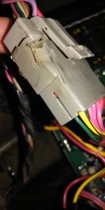
Idle current: My cheap multi-meter has very thin leads so I don't dare try it. The Yellow/black wire in the photo is the power input and it is very hot all the time at the connector and is the reason the connector has partly melted.
I cannot be sure both modules are heating up as the cooling fins run across both of them. It could just be the front module.
Front module:
pins 1 to 7: 0.03v
pins 10 to 16: 0.76v
Rear module:
pins 1 to 7: 0.7v
pins 10 to 16: 0.78v
Idle current: My cheap multi-meter has very thin leads so I don't dare try it. The Yellow/black wire in the photo is the power input and it is very hot all the time at the connector and is the reason the connector has partly melted.
I cannot be sure both modules are heating up as the cooling fins run across both of them. It could just be the front module.
Attachments
Yes it is. I also just confirmed that it is the LF speaker that is open circuit. The RF speaker measures 5.6 ohms and actually does produce some distorted sound.
Can you desolder the power pins for the channel with DC across it to see if the amp will otherwise function normally?
I removed the whole module. Put the board back on the heat sink and now have no power. The module came off clean so I likely damaged something by handling the board rather than desoldering. It now looks like this:
STK Pin 2: 1.3v
STK Pin 6: 0v
TL594 pin 12: 9.5v
7815 pin 1: 1.3v
7915 pin 3: 0v
The TO220 rectifiers test ok and the mosfets test ok on the board.
I have it apart again and am trying to trace the back of the board to see where the power goes.
STK Pin 2: 1.3v
STK Pin 6: 0v
TL594 pin 12: 9.5v
7815 pin 1: 1.3v
7915 pin 3: 0v
The TO220 rectifiers test ok and the mosfets test ok on the board.
I have it apart again and am trying to trace the back of the board to see where the power goes.
9.5v is low. I don't know if the amp has low-voltage protection. I would expect pin 12 to be near the supply voltage for the amp. I don't know what you know about the 594 so ask questions if you have any about its operation.
There's a sample circuit here http://circuitsan.blogspot.com/2013/09/tl594-12v-dc-switch-mode-power-supply.html, but this amp is a little different. Pins 11 and 12 are tied together and pass through a 47 ohm resistor to the emitter of an 2N3904 NPN transistor. The collector disappears underneath the transformer and I am still trying to figure out where the base goes.
The 3904 may be passing 12v from the main B+ wire to the 594.
What's the DCV on pin 14 of the 594?
What's the DCV on pin 14 of the 594?
It will likely save time to get all of the 594 voltages. Copy and paste the following list and fill in the blanks. If there is no blank space after the colon, add one between the colon and the numbers you enter. It makes it much easier to read.
Pin 1:
Pin 2:
Pin 3:
Pin 4:
Pin 5:
Pin 6:
Pin 7:
Pin 8:
Pin 9:
Pin 10:
Pin 11:
Pin 12:
Pin 13:
Pin 14:
Pin 15:
Pin 16:
Pin 1:
Pin 2:
Pin 3:
Pin 4:
Pin 5:
Pin 6:
Pin 7:
Pin 8:
Pin 9:
Pin 10:
Pin 11:
Pin 12:
Pin 13:
Pin 14:
Pin 15:
Pin 16:
Pin 1: 4.41Pin 1: 4.41
Pin 2: 0.47
Pin 3: 4.42
Pin 4: 1.88
Pin 5: 1.5
Pin 6: 3.32
Pin 7: 0.01
Pin 8: 9.49
Pin 9: 0.01
Pin 10: 0.01
Pin 11: 9.49
Pin 12: 9.49
Pin 13: 4.75
Pin 14: 4.76
Pin 15: 0.47
Pin 16: 0.43
Pin 2: 0.47
Pin 3: 4.42
Pin 4: 1.88
Pin 5: 1.5
Pin 6: 3.32
Pin 7: 0.01
Pin 8: 9.49
Pin 9: 0.01
Pin 10: 0.01
Pin 11: 9.49
Pin 12: 9.49
Pin 13: 4.75
Pin 14: 4.76
Pin 15: 0.47
Pin 16: 0.43
The pin 1/2 error amp input is driving pin 3 high and shutting down the IC.
Could you possibly have a solder bridge between any of the terminals for the IC you removed?
Can you see what pins 1 and 2 connect to?
Could you possibly have a solder bridge between any of the terminals for the IC you removed?
Can you see what pins 1 and 2 connect to?
No solder bridges. I just checked using the ohm meter pin to pin just in case my eyes missed something.
Pin 1: 2.4K resistor which connects to ground.
Pin 2: Connects to pin 15 and the collector of a TIP 31C NPN power transistor, (In the diagram above I mistakenly had it connected to the base)
Pin 1: 2.4K resistor which connects to ground.
Pin 2: Connects to pin 15 and the collector of a TIP 31C NPN power transistor, (In the diagram above I mistakenly had it connected to the base)
- Home
- General Interest
- Car Audio
- Another Ford JBL Amplifier