Hi all.
I just finished reading almost all of the monster DIY turntable thread, which seems to have ground to a halt last September. Some really great ideas: air bearings, magnetic bearings, floating the platter on oil... great stuff.
Each approach has its problems: Air bearings need top-flite precision and a compressor (or pressurized air source), magnetic bearings need suitable magnets and have all kinds of magnetic field issues, floating on oil could be messy and the difficulty of keeping the platter centered while applying a driving force remains to be solved.
I have been thinking about this problem tho - what we need is an approach that is 1) simple 2) plays LPs well and 3) is buildable.
Also, on looking at the various designs currently in use, it appears that we have become collectively fixated on the idea tha we have to apply the rotational force directly to the platter. Most of the inherent limitations in turntables comes from this basic design feature.
Whenever I have to solve a problem, I tend to look around to see if humans have already solved it. Looking back, it did not appear that any device simmilar to a hifi turntable had been needed or used in human history - until I noticed the Potter's Wheel.
This device uses a very coarse motive force (the potter's feet) and translates it into a very fine rotational machine, capable of amazing precision - and, it is very simple.
This approach has some really attractive features:
1) the rotational force is applied to a flywheel which can be decoupled from the platter in all sorts of ways while maintaining precise speed control
2) any vibrations derived from drive mechanism (motor) can be isolated from the LP/platter interface.
3) the mass of the platter can be configured to best suit the dynamics of playing LPs, not rotating them.
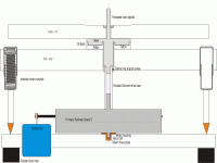
I have attached a first kick at the idea of designing a TT on the principals of a potter's wheel. I'm sure many of you could come up with a better interpretation.
I will look forward to comments on this idea - hope it rings a bell with some of you like it has with me.
HNY
Jess
I just finished reading almost all of the monster DIY turntable thread, which seems to have ground to a halt last September. Some really great ideas: air bearings, magnetic bearings, floating the platter on oil... great stuff.
Each approach has its problems: Air bearings need top-flite precision and a compressor (or pressurized air source), magnetic bearings need suitable magnets and have all kinds of magnetic field issues, floating on oil could be messy and the difficulty of keeping the platter centered while applying a driving force remains to be solved.
I have been thinking about this problem tho - what we need is an approach that is 1) simple 2) plays LPs well and 3) is buildable.
Also, on looking at the various designs currently in use, it appears that we have become collectively fixated on the idea tha we have to apply the rotational force directly to the platter. Most of the inherent limitations in turntables comes from this basic design feature.
Whenever I have to solve a problem, I tend to look around to see if humans have already solved it. Looking back, it did not appear that any device simmilar to a hifi turntable had been needed or used in human history - until I noticed the Potter's Wheel.
This device uses a very coarse motive force (the potter's feet) and translates it into a very fine rotational machine, capable of amazing precision - and, it is very simple.
This approach has some really attractive features:
1) the rotational force is applied to a flywheel which can be decoupled from the platter in all sorts of ways while maintaining precise speed control
2) any vibrations derived from drive mechanism (motor) can be isolated from the LP/platter interface.
3) the mass of the platter can be configured to best suit the dynamics of playing LPs, not rotating them.
I have attached a first kick at the idea of designing a TT on the principals of a potter's wheel. I'm sure many of you could come up with a better interpretation.
I will look forward to comments on this idea - hope it rings a bell with some of you like it has with me.
HNY
Jess
Attachments
Too many links in the (drive) chain and alot of bearings IMO.
The subplatter could be driven directly somehow thus loseing the rubber belt from the motor.
The silicone tube....again a possible source of speed variations in the main platter due to stylus drag?
I think there could be mileage in the idea. Heavy subplatter for speed stability driving a light main platter for low energy storage/dispersion.
Paul.
I think there could be mileage in the idea. Heavy subplatter for speed stability driving a light main platter for low energy storage/dispersion.
Yep, thats the essence of the idea.
Too many links in the (drive) chain and alot of bearings
There are only two bearings in the design as it is. The one supporting the flywheel and the one supporting the platter. However, you may have a point. The concentric bearing for the platter is the least developed part of the concept at this point. Im hoping that some of thr mrchanical wizards out there will come in and help figure it out

Any and all suggestions welcome...
Lets see what develops
Jess
Hi!
Have a look at the Forsell Air Ref. w flyweel drive. The flyweel is rotatinf at a speed of app. 1500 rpm and is made of brass. this in turn drives the relatively light main platter. If we make the (correct or incorrect) assumption that we have a stiff connection between the flyweel and the platter we get a system that have the inertia equivalent of a platter at 33 rpm with a mass of close to 1 ton, interresting!
BR,
Anders
JesseG said:Hi all.
1) the rotational force is applied to a flywheel which can be decoupled from the platter in all sorts of ways while maintaining precise speed control
How can one maintain precise speed control with decoupling? Paul is right, the flexure of the tube you suggest will inherently allow speed fluctuations.
bappe said:Hi!
Have a look at the Forsell Air Ref. w flyweel drive. The flyweel is rotatinf at a speed of app. 1500 rpm and is made of brass. this in turn drives the relatively light main platter. If we make the (correct or incorrect) assumption that we have a stiff connection between the flyweel and the platter we get a system that have the inertia equivalent of a platter at 33 rpm with a mass of close to 1 ton, interresting!
BR,
Anders
I would have to assume that the belt is not a stiff connection between the flywheel and the platter, same problem as the flexible tube.
This flywheel idea was discussed in a recent thread. (light weight plinth?) Paul, did you start it?
Like many things in audio, just because it has been done, does not make it a good idea.
What's wrong with regular old belt drive?
I suppose direct drive is out of the question for DIY.
Max
Hi Jesse and others,
Looks a bit as the Transrotor magnetic drive. In stead of the silicone tube spring they use a magnetic spring as coupler. But such an extra mass and spring introduce an extra mass-spring system with an extra resonance to cope with.
All those mass-spring things are exited by the varying drag of the groove modulation. IMHO a heavy platter which is simply loosely belt driven by a steady running motor still appears to me as the most optimum compromise.
The air coupled flywheel looks very interesting. But I don’t think this will give the platter a very high effective mass. It is simply de mass of the platter (-> moment of inertia) driven by the torque as a result of the drag of the coupling air between platter and flywheel.
Cheers 😉
For the first design mentioned in this topic I would like to point at the risk of torsion resonance. Kind of overshoot- effect: the response after a sudden increase in stylus drag.
Can be compaired to the main drawback of a bass- reflex speaker.
Oh, by the way I build my own arms and motor units too. In the gallery of V. Engine Y'l find my unipivot balsa- arm.
And at the moment I'm working on a heavy TD160- based motor unit: no floating subchassis but a stationairy one.
Can be compaired to the main drawback of a bass- reflex speaker.
Oh, by the way I build my own arms and motor units too. In the gallery of V. Engine Y'l find my unipivot balsa- arm.
And at the moment I'm working on a heavy TD160- based motor unit: no floating subchassis but a stationairy one.
Very ineresting comments from all.
Thanks for this, Anders. Shows me that soemone else has seen enough merit in the idea to build one.
Yes, I can see the possibility of getting some effect from that. I expect that some experimentation could identify a suitable drive coupling material.
I just really want to find a way to get away from applying the rotational force directly to the platter, thus avoiding all of the latteral force complications that derive from that one engineering compromise.
Let's see what else folks come up with 😎
Jess
Have a look at the Forsell Air Ref. w flyweel drive. The flyweel is rotatinf at a speed of app. 1500 rpm and is made of brass. this in turn drives the relatively light main platter. If we make the (correct or incorrect) assumption that we have a stiff connection between the flyweel and the platter we get a system that have the inertia equivalent of a platter at 33 rpm with a mass of close to 1 ton, interresting!
Thanks for this, Anders. Shows me that soemone else has seen enough merit in the idea to build one.
All those mass-spring things are exited by the varying drag of the groove modulation
Yes, I can see the possibility of getting some effect from that. I expect that some experimentation could identify a suitable drive coupling material.
I just really want to find a way to get away from applying the rotational force directly to the platter, thus avoiding all of the latteral force complications that derive from that one engineering compromise.
Let's see what else folks come up with 😎
Jess
JesseG said:I just really want to find a way to get away from applying the rotational force directly to the platter, thus avoiding all of the latteral force complications that derive from that one engineering compromise.
Let's see what else folks come up with 😎
Jess
Okay,
How about a motor that revolves at 33.3 RPM attached directly to the flexible drive shaft-tube thing. No lateral load and no coupled flywheel transient issues.
I suppose one could mock this up with a DIY platter hovering over a direct drive table with a piece of tubing wedged over the spindle and attached to the underside of the DIY platter.
Or, how about a belt riding around the motor and two idler pulleys forming an equalateral triangle around the platter. No lateral load on the platter, and it has been done before. Just don't use three motors.
Max
How about a motor that revolves at 33.3 RPM attached directly to the flexible drive shaft-tube thing. No lateral load and no coupled flywheel transient issues.
Now that is a good idea! Easy to build and test as you say using an existing DD table - which we all know are good for nothing else

I'm going to build this. I'll let you all know how it turns out.
Thanks, Max
Jess
Hi Jess,
For your interest, have also a look at the magnetic coupler/spring from Transrotor:
http://www.efco.ch/Ue/produkte/transrotor/TMD-Lager.pdf
Although it is in German, the drawing is clear enough.
Cheers 😉
For your interest, have also a look at the magnetic coupler/spring from Transrotor:
http://www.efco.ch/Ue/produkte/transrotor/TMD-Lager.pdf
Although it is in German, the drawing is clear enough.
Cheers 😉
Thanks, Pjotr...
Interesting. I wonder how well it works. I was reading somewhere else that the magnets can induce a pulsing into the platter when the magnetic poles pass (or at least that's what I think they meant).
Thinking about all of the bearing / drive combinations people have come up with (air bearings, mags, etc.), some of them have only one drawback - the require exceptional skill and resources to build them.
I have been looking for a 'good' tt design which can be built by most any determined DIY'er.
Cheers
Jess
JesseG said:Thanks, Pjotr...
Interesting. I wonder how well it works. I was reading somewhere else that the magnets can induce a pulsing into the platter when the magnetic poles pass (or at least that's what I think they meant).
The magnets “hold” steadily when the table spins. So I see no pulsing problem. There can be pulsing to the pick-up element but when the parts are made from thick soft steel I don’t think there is much influence. When de magnets are surrounded by a small copper/aluminium ring there is also a means of effective damping of the mass-spring system by eddy currents in the ring.
I have been looking for a 'good' tt design which can be built by most any determined DIY'er.
For a good diy turntable you should have at least access to a suitable lathe and possible also a milling machine to be successful IMHO. Not many diy'ers will do I think.
Cheers 😉
- Status
- Not open for further replies.
- Home
- Source & Line
- Analogue Source
- Another DIY Turntable - maybe a new idea?