Here is my take on a balanced input phono-amplifier…
For some reason I had to investigate the function of the Improved Howland Current Source (IHCS) and so I got the idea to use this principle for a RIAA amp.
I don’t want to explain the IHCS here but there’s a lot to find about it in the web. This is a good reading to start with: AN-1515 A Comprehensive Study of the Howland Current Pump
The design-features in some steps:
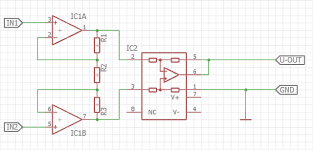
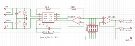
1. Composite Instrumentation Amplifier (INA)

Using a composite INA hast the advantage that the first Opamps (IC1) can be optimized for the source impedance, ie. JFET-Input Opamps for MM and BJT- Input Opamps for MC cartridges.
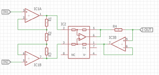
2. Improved Howland Current Source
Adding a few components converts the INA to an IHCS, note that it has a current output:

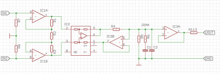
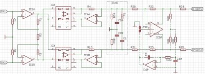
3. Completed Phono-Preamp
Now we only need an RIAA network and a buffer to make it complete:

Components:
IC1 should be optimized for the source impedance.
IC2 can be a THAT1240, INA134 or the like.
IC3, especially IC3B should be optimized for low input bias current and low output offset.
There are several knobs to set the gain of this circuit:
The input stage (IC1, R1…R3) should be laid out for high gain when used as a MC amp. For my high-output MC I currently use a gain of 50x in this stage.
IC2: INA134 and THAT1240 are unity gain but THAT1246 can be set up for up to 2x gain.
R4 sets the transimpedance of the IHCS and the impedance of the RIAA network determines the final output voltage. So the combination of transimpedance, respectively output current of the IHCS in combination with the final impedance of the RIAA network gives the possibility to adjust gain as well.
Of cause IC3A could also be configured to add some gain.
Until now I tested two different RIAA networks, one with an impedance of ~10kOhm @ 1kHz and one with ~1kOhm @ 1kHz. The transimpedance has been adjusted to give the same overall amplification. To me the lower impedance RIAA network sounded better.
So at present I have a gain of 50x in the first stage around IC1, and a transimpedance of 20mA/V (R4= 50Ohm) into 1kOhm RIAA-network. My Cartridge has 2mV output.
Input-stage: 2mV output from my cartridge x 50 =100mV
Transimpedance-stage: 100mV --> 2mA
Voltage over RIAA-Network: 2mA x 1kOhm = 2V
There are certainly better gain-distributions possible, but that’s how I made the first test and I’m very pleased with the result so far. I did not make any simulation of all that btw.
...
For some reason I had to investigate the function of the Improved Howland Current Source (IHCS) and so I got the idea to use this principle for a RIAA amp.
I don’t want to explain the IHCS here but there’s a lot to find about it in the web. This is a good reading to start with: AN-1515 A Comprehensive Study of the Howland Current Pump
The design-features in some steps:
1. Composite Instrumentation Amplifier (INA)
Using a composite INA hast the advantage that the first Opamps (IC1) can be optimized for the source impedance, ie. JFET-Input Opamps for MM and BJT- Input Opamps for MC cartridges.
2. Improved Howland Current Source
Adding a few components converts the INA to an IHCS, note that it has a current output:
3. Completed Phono-Preamp
Now we only need an RIAA network and a buffer to make it complete:
Components:
IC1 should be optimized for the source impedance.
IC2 can be a THAT1240, INA134 or the like.
IC3, especially IC3B should be optimized for low input bias current and low output offset.
There are several knobs to set the gain of this circuit:
The input stage (IC1, R1…R3) should be laid out for high gain when used as a MC amp. For my high-output MC I currently use a gain of 50x in this stage.
IC2: INA134 and THAT1240 are unity gain but THAT1246 can be set up for up to 2x gain.
R4 sets the transimpedance of the IHCS and the impedance of the RIAA network determines the final output voltage. So the combination of transimpedance, respectively output current of the IHCS in combination with the final impedance of the RIAA network gives the possibility to adjust gain as well.
Of cause IC3A could also be configured to add some gain.
Until now I tested two different RIAA networks, one with an impedance of ~10kOhm @ 1kHz and one with ~1kOhm @ 1kHz. The transimpedance has been adjusted to give the same overall amplification. To me the lower impedance RIAA network sounded better.
So at present I have a gain of 50x in the first stage around IC1, and a transimpedance of 20mA/V (R4= 50Ohm) into 1kOhm RIAA-network. My Cartridge has 2mV output.
Input-stage: 2mV output from my cartridge x 50 =100mV
Transimpedance-stage: 100mV --> 2mA
Voltage over RIAA-Network: 2mA x 1kOhm = 2V
There are certainly better gain-distributions possible, but that’s how I made the first test and I’m very pleased with the result so far. I did not make any simulation of all that btw.
...
Attachments
-
 Screenshot - 08_001 - Kopie.png37.7 KB · Views: 960
 -
 Screenshot - 08_002 - Kopie.png42.5 KB · Views: 905
 -
 Screenshot - 08_003 - Kopie.png68.6 KB · Views: 1,147
 -
 Screenshot - 08_004 - Kopie.png132.1 KB · Views: 831
 -
 Screenshot - 08_005 - Kopie.png249 KB · Views: 765
 -
 Screenshot - 08_006 - Kopie.png205.2 KB · Views: 767
 -
 Screenshot - 08_008 - Kopie.png80.2 KB · Views: 759
 -
 Screenshot - 08_009 - Kopie.png146.1 KB · Views: 749
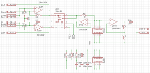
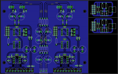
The PCB:
This is my experimental version that I’m actually listening to. The RIAA network is on a piggy-back-board and connected with a 10-pin header. The board is dual mono and contains a simple discrete shunt regulator for each channel. Output-offset is a couple of tens millivolt, which I can tolerate in my system. The big connector on the front end allows for external gain- and load resistors.
There are some other features on the board which I explain later.

The board looks like this (top layer red/ bottom layer blue)


...
This is my experimental version that I’m actually listening to. The RIAA network is on a piggy-back-board and connected with a 10-pin header. The board is dual mono and contains a simple discrete shunt regulator for each channel. Output-offset is a couple of tens millivolt, which I can tolerate in my system. The big connector on the front end allows for external gain- and load resistors.
There are some other features on the board which I explain later.
The board looks like this (top layer red/ bottom layer blue)
...
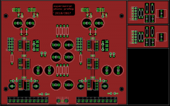
Meanwhile I made a much simpler board which I have not populated yet. It uses a THAT1512 as input device and is probably better suited for MC cartridges:

The load resistor is external connected and the output has an impedance-balanced and a single-ended option.
Again: I have not tested this circuit. If the output-offset is too high I might consider an additional DC-servo.
This board contains also a simple shunt-reg and piggy-back RIAA network. The PCB single-sided and thus more diy-friendly.
It takes half of a E100 board for a stereo pair

Any comments and questions are welcome!
Cheers, Boris
The load resistor is external connected and the output has an impedance-balanced and a single-ended option.
Again: I have not tested this circuit. If the output-offset is too high I might consider an additional DC-servo.
This board contains also a simple shunt-reg and piggy-back RIAA network. The PCB single-sided and thus more diy-friendly.
It takes half of a E100 board for a stereo pair
Any comments and questions are welcome!
Cheers, Boris
- Status
- Not open for further replies.