I'm prototyping version 3 of a 4 x KT88 PPP Amp.
Looking at some historical designs I see several designs which run 47 Ohm resistors in each output tube anode.
Is this for stability or an attempt to get the tubes to current share (balance) ?
If for balance then the 10 ohm resistors I use in each cathode would do the same thing (ONLY better) - right?
Any opinion gratefully received.
Cheers,
Ian
Hi,
Works not unlike gridstopper resistors but far less common.
Often called "plate resistor".
Cheers, 😉
Looking at some historical designs I see several designs which run 47 Ohm resistors in each output tube anode.
Works not unlike gridstopper resistors but far less common.
Often called "plate resistor".
Cheers, 😉
Stability
Some older '40s & '50s amps used an inductor of 1/4" dia x 3/4" long with about 20 turns of #20 guage wire on PPP designs. This stopped high frequency instability above the audio range.
Some older '40s & '50s amps used an inductor of 1/4" dia x 3/4" long with about 20 turns of #20 guage wire on PPP designs. This stopped high frequency instability above the audio range.
Hi !
For a long time I contemplate for designing something using this topology (If I don't mistake, another name for CIRCLOTRON).
It seems to me that the worst offender (not to speak about huge drive requirement) is the necessity in having the two HV supply floating, not only at DC but at AC too.
I mean that the parasitic capacitance of those supplies vs ground should (MUST ? ) be kept as lo as possible, cos they are at the AC potential of the output tubes's plates wich is an HOT signal point.
I beleive in turn, that a standard power supply tranny cannot be used, rather it must be built with the lowest possible capacitance from the HV windings to all others.
In other words, some relaxed requirements for the OPT are moved to the PSU tranny.
Of course, SS rectification and simple RC smoothing may help, in eliminating the capacitance of valves's heather windings to ground, and the need of having the chokes floating too.
Could this explain the need for "plate stoppers" ?
Just a thought.
Yves.
Not really- the PS is at AC ground anyway. On top of that, the feed is to a push-pull point, the OPT's center tap. This is just a way to knock down the Q at the high voltage (AC) points from wiring and the OPT. One amp I saw used parallel output tubes, with the plate stoppers only in the leads of the tubes furthest from the transformer.
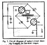
I can't agree with that, it seems to me that PSU are at plate potential. (See attached)SY said:Not really- the PS is at AC ground anyway.
Attachments
SY said:One amp I saw used parallel output tubes, with the plate stoppers only in the leads of the tubes furthest from the transformer.
I've noticed that in alot of PPP schematics I've looked at on the web.
One pair of tubes has plate chokes,while the others don't..always seemed a little odd to me,and I wonderered why they didn't just put plate chokes on all the pairs of tubes.(Some schema's do show plate chokes on all the output tubes.)
gingertube said:I'm prototyping version 3 of a 4 x KT88 PPP Amp.
Looking at some historical designs I see several designs which run 47 Ohm resistors in each output tube anode.
Is this for stability
yes..........resistors act as RF parasitic dampers used with high gm tubes.....I replaced some in an amp with the modern type of film power resistors ..this was a mistake as they are spirally cut and act as mini inductors.
Replace with carbon composition types (if you can find them)otherwise one risks HF parasitic oscillation especially when the tube output loading tips toward class B in an AB amp....it's usually an indication of an older generation output tranny with higher leakage inductance and capacitance.
richj
- Status
- Not open for further replies.
- Home
- Amplifiers
- Tubes / Valves
- Anode Resistors on PPP Amps