http://www.fortunecity.com/rivendell/xentar/1179/projects/aaphono/aaphono.html
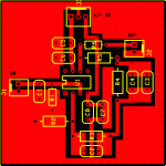
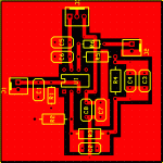
This is my first attempt at designing a PCB so go easy ok Its the Analog Addicts preamp without the coupling caps on the output. The resistors in the feedback loop are physically larger because the schematic calls for .1% tolerance. The .0047uf and .001uf caps are Wima MKP2 while the 47pf and 330pf are ceramic. Although maybe switching to polystyrene could improve things.
This layout was done with ExpressPCB although I am trying to learn Protel. The learning curve is a bit steep. Any comments or criticisms are welcome.
Attachments
I would like to see the J-fet put in😉 Otherwise it looks good if you get the C's right as Eva said.(I didnt check😉 )Any comments or criticisms are welcome.
Steen🙂
Edit If you call this "El Cheapo" You have to make room for some Elyt's!! Thorsten used loads of decoupling on that one🙂
Konnichiwa,
There is no 47pF capacitor in the schematic and the 330pF capacitor is in the Equaliser circuit, ceramic is not acceptable.
The Equaliser capacitors should be as good as you can manage, polystyrene is par for the course and FKP is already pretty shoddy. Ceramic - there is no word for this I can use here.
You might want to allow for a range of capacitor sizes for all the various types.
As for the PCB, consider doing without, PCB's are really nasty things.
Past that, remember that unless you reliably can galvanically separate both channels supplies you need to arrange the circuit with a "single point ground" for the output section, so your single channel PCB is a poor choice as well for that.
Sayonara
astouffer said:[while the 47pf and 330pf are ceramic.
There is no 47pF capacitor in the schematic and the 330pF capacitor is in the Equaliser circuit, ceramic is not acceptable.
The Equaliser capacitors should be as good as you can manage, polystyrene is par for the course and FKP is already pretty shoddy. Ceramic - there is no word for this I can use here.
You might want to allow for a range of capacitor sizes for all the various types.
As for the PCB, consider doing without, PCB's are really nasty things.
Past that, remember that unless you reliably can galvanically separate both channels supplies you need to arrange the circuit with a "single point ground" for the output section, so your single channel PCB is a poor choice as well for that.
Sayonara
steenoe said:If you call this "El Cheapo" You have to make room for some Elyt's!!
Thorsten used loads of decoupling on that one🙂
I agree you have to take very good attention to power supply
if you use the MC part of this circuit.
JFET circuit is a good example of very low PSRR, power supply rejection ratio.
JFET uses +12V only.
Nearly any garbage signal in +12V line will go through
2.2k - 1uF - 681k and be amplified in OP-amp.
This doesnt make it a bad circuit, if you use a very good +12V supply.
And make a good practical wiring between components.
Notice 10H filter inductor in positive rail! (Shouldnt this be 10mH ??)
And the fact that full Star-grounding is recommended.
Finally a part of Thorsten Loesch important words about PSU:
Finally, the Layout of the Circuit is Dual-Mono and uses full Star-grounding.
My current implementation feeds of the Amp's PSU, which is external and uses Batteries.
The Voltage is taken from the + and -12-Volt "tap's" on the Battery stack.
I cannot recommend any type of regulated supplies.
You MUST use Batteries to have the full performance possible with this circuit.
May I humbly recommend the Yusea NP Series 12Volt 2.1 Ah sealed Lead Acid Batteries (or eqivalents).
These should be charged in parallel.
Konnichiwa,
No, it is meant to be 10H.
I used fairly small size, low current pot core types from
www.steinmusic.de.
As you rightly remarked, the J-Fet stage operates at VERY low signal levels and has for intent and purpose zero PSRR. The combination of 10H & 2200uF do knock any PSU Rail Noise quite flat and shifts any resonances to extremely low supersonic frequencies, well damped....
At 100Hz the choke has around 6kOhm Impedance, the 2,200uF Capacitor 0.7 Ohm. This gives around 80db passive PSRR on a PSU line that should have fractions of a millivolt noise anyway, at 100Hz, less at lower frequencies more at higher ones....
Nominal Level at the junction is 5mV, so 5mV PSU Rail noise would lead to a S/N Ratio of around 80db unless very low frequency noise is present.
Sayonara
lineup said:Notice 10H filter inductor in positive rail! (Shouldnt this be 10mH ??)
No, it is meant to be 10H.
I used fairly small size, low current pot core types from
www.steinmusic.de.
As you rightly remarked, the J-Fet stage operates at VERY low signal levels and has for intent and purpose zero PSRR. The combination of 10H & 2200uF do knock any PSU Rail Noise quite flat and shifts any resonances to extremely low supersonic frequencies, well damped....
At 100Hz the choke has around 6kOhm Impedance, the 2,200uF Capacitor 0.7 Ohm. This gives around 80db passive PSRR on a PSU line that should have fractions of a millivolt noise anyway, at 100Hz, less at lower frequencies more at higher ones....
Nominal Level at the junction is 5mV, so 5mV PSU Rail noise would lead to a S/N Ratio of around 80db unless very low frequency noise is present.
Sayonara
The input cap depends on what the cartridge is spec'd for. In this case its 47pf. You are right about the ceramic caps though, nobody has anything good to say about them. That leaves polystyrene and silver mica.
This wasn't meant to be a direct copy of the schematic. Its been tailored to fit my needs. I always thought high gain opamps benefitted from using a pcb? Keeps all the traces short and paths direct. It shouldn't be too hard to mirror this layout and make a dual channel single board.
This wasn't meant to be a direct copy of the schematic. Its been tailored to fit my needs. I always thought high gain opamps benefitted from using a pcb? Keeps all the traces short and paths direct. It shouldn't be too hard to mirror this layout and make a dual channel single board.
Konnichiwa,
Ahh, if it is the cartridge load, fine. Again, please avoid ceramics, I specify standard styrene's as minimum. Silver Mica's can sound bad, it seems to be brand dependent.
Direct Hardwiring "dead bug style" on asolid piece of copper can have even shorter path and has guaranteed no leakage. FR4 PCB material is really hygroscopic and changes behaviour with weather and soaks up moisture during etching, standard pertinax is worse.
If you can get PTFE PCB's go for PCB, otherwise consider hardwiring using either copper substrat or make your own "baseboard" from a small PTFE Sheet. with some stick on (arts supply) copper tape as groundplane.
Yup, if you must, go for it.
Sayonara
astouffer said:The input cap depends on what the cartridge is spec'd for. In this case its 47pf. You are right about the ceramic caps though, nobody has anything good to say about them. That leaves polystyrene and silver mica.
Ahh, if it is the cartridge load, fine. Again, please avoid ceramics, I specify standard styrene's as minimum. Silver Mica's can sound bad, it seems to be brand dependent.
astouffer said:I always thought high gain opamps benefitted from using a pcb? Keeps all the traces short and paths direct.
Direct Hardwiring "dead bug style" on asolid piece of copper can have even shorter path and has guaranteed no leakage. FR4 PCB material is really hygroscopic and changes behaviour with weather and soaks up moisture during etching, standard pertinax is worse.
If you can get PTFE PCB's go for PCB, otherwise consider hardwiring using either copper substrat or make your own "baseboard" from a small PTFE Sheet. with some stick on (arts supply) copper tape as groundplane.
astouffer said:It shouldn't be too hard to mirror this layout and make a dual channel single board.
Yup, if you must, go for it.
Sayonara
- Status
- Not open for further replies.
- Home
- Amplifiers
- Solid State
- Analog Addict's (El Cheapo) PCB

