As a happy Quad 63 listener, Dipole-DIY-er and fascinated by the AMT Mid-Tweeters ... why not face the challenge to mix that all together into yet another, this time slighty more experimental DIY project for me: A non-standard AMT with an electrostatic drive ...
ES_AMT_1.jpg
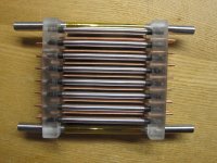
I started with the Idea of a folded AMT-curtain which would have some 4:1 depth-to-width ratio and would result in some sort of max. 4:1 compression ratio, if the membrane would perfectly move in parallel (which is not the case). I designed not much deeper, because of possible lambda/4-resonances.
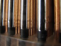
The membrane is hold into it's curtain shape by carbon rods which are manteled by shrinking tube. These rods can rotate in the plexyglass holders so to allow some repartition of the membrane tension.
ES_AMT_4.jpg
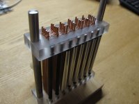
On both sides of the array there is a V2A steel rod, letting stretch the membrane and slightly play with the tension. After the tension seems ok, the membrane has been further stretched with a hot air gun. The electrostatic load of the membrane is fed by one of these V2A rods.
ES_AMT_2.jpg
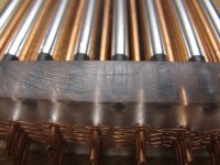
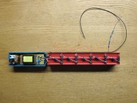
Each fold of the electrostatically charged membrane has on both sides 5 straight copper wires driving the audio signal to it. Because everything should be symmetric, in theory there would not be any lateral forces on these copper wires. Wirewise, a wire either pushes, or pulls both adjacent menbrane folds. All these 5-Wires-Arrays are alternatively fed by the high tension audio signal. One set is fed from the top, the other set with opposite polarity from the bottom. The distance from these arrays to the membrane is some 2mm, as everything is set up on a raster of 2.54mm.
ES_AMT_3.jpg
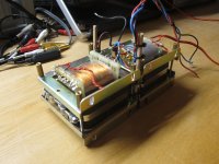
The transformers are 220V-5V types, which gives a theoretical ratio of 1:44 when inversely used. To archieve enough high Audio signal Voltage, two of them are used, totalling to a ratio of 1:88. In order to get some 4kV audio signal, the nominal 5V inputs of the transformers must be fed with some tenfold 45V...50V. Therefore, to avoid saturation of the iron core, this setup must not be fed with signals below the tenfold of the nominal 50Hz, e.g. not below 500Hz.
Transformers.jpg
The static high voltage is provided by a Cockcroft-Walton multiplyer, fed by a commercial inverter for cold cathode lighting, the latter outputting 700V ... 1100V / 5mA at a frequency of 30kHz. The diodes are 2kV/3A types, the capacitors are Wima MKS 2kV/100nF types. So at the end of the miltiplyer chaint there must approx. be some 4kV.
CockcroftWalton.jpg
So, hooking all together ... and driving it with an old faithful Yamaha AX 590.
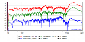
Three different membranes have been measured. Twice (red/green) membranes cut out from an aluminium damped emergency blanket. KISS for the beginning, because it is a standarded and readily available (I know, I know, way too much conductivity ...). This kind of membrane material is very noisy by itself, very self-resonant, which leads to really messed-up acoustic results between 500Hz ... 5kHz, full of resonances. And also a huge and broad peaking above 10kHz. Because of these resonances, something completely different was used for a third attempt: Give it a chance with a self-adhesive aluminium ribbon, all along with it's protective PE-strip-off-layer (blue). This provides a nice self-damping sandwich membrane, a much smoother sweep audition, but an akward loss of SPL around 10kHz. So in the end, none of these two membranes were suitable. And I am reluctant to dive into self.made soap/graphite/magicmixtures coating of unobtainable membrane brands. Unless someone knows THE solution ...
Amplitude.png
Besides the resonances there was way too low SPL: 80dB, and when driving it louder, then the sparks went firing ... for the case of the safety blanket, each spark was evaporating some of the aluminium coating (sort of a nice self-limiting process, indeed). The foil itself was robust: The sparking was not punching a hole into the foil.
Membrane.jpg
So all in all the project is/was a fail until now. But it was fun, and I learned a lot about electrostatic LS. And I luckily am still alive, despite handling HT.
I have not given up completely, though: Maybe someone has some most welcomed constructive critics / remarks / hints?
ES_AMT_1.jpg
I started with the Idea of a folded AMT-curtain which would have some 4:1 depth-to-width ratio and would result in some sort of max. 4:1 compression ratio, if the membrane would perfectly move in parallel (which is not the case). I designed not much deeper, because of possible lambda/4-resonances.
The membrane is hold into it's curtain shape by carbon rods which are manteled by shrinking tube. These rods can rotate in the plexyglass holders so to allow some repartition of the membrane tension.
ES_AMT_4.jpg
On both sides of the array there is a V2A steel rod, letting stretch the membrane and slightly play with the tension. After the tension seems ok, the membrane has been further stretched with a hot air gun. The electrostatic load of the membrane is fed by one of these V2A rods.
ES_AMT_2.jpg
Each fold of the electrostatically charged membrane has on both sides 5 straight copper wires driving the audio signal to it. Because everything should be symmetric, in theory there would not be any lateral forces on these copper wires. Wirewise, a wire either pushes, or pulls both adjacent menbrane folds. All these 5-Wires-Arrays are alternatively fed by the high tension audio signal. One set is fed from the top, the other set with opposite polarity from the bottom. The distance from these arrays to the membrane is some 2mm, as everything is set up on a raster of 2.54mm.
ES_AMT_3.jpg
The transformers are 220V-5V types, which gives a theoretical ratio of 1:44 when inversely used. To archieve enough high Audio signal Voltage, two of them are used, totalling to a ratio of 1:88. In order to get some 4kV audio signal, the nominal 5V inputs of the transformers must be fed with some tenfold 45V...50V. Therefore, to avoid saturation of the iron core, this setup must not be fed with signals below the tenfold of the nominal 50Hz, e.g. not below 500Hz.
Transformers.jpg
The static high voltage is provided by a Cockcroft-Walton multiplyer, fed by a commercial inverter for cold cathode lighting, the latter outputting 700V ... 1100V / 5mA at a frequency of 30kHz. The diodes are 2kV/3A types, the capacitors are Wima MKS 2kV/100nF types. So at the end of the miltiplyer chaint there must approx. be some 4kV.
CockcroftWalton.jpg
So, hooking all together ... and driving it with an old faithful Yamaha AX 590.
Three different membranes have been measured. Twice (red/green) membranes cut out from an aluminium damped emergency blanket. KISS for the beginning, because it is a standarded and readily available (I know, I know, way too much conductivity ...). This kind of membrane material is very noisy by itself, very self-resonant, which leads to really messed-up acoustic results between 500Hz ... 5kHz, full of resonances. And also a huge and broad peaking above 10kHz. Because of these resonances, something completely different was used for a third attempt: Give it a chance with a self-adhesive aluminium ribbon, all along with it's protective PE-strip-off-layer (blue). This provides a nice self-damping sandwich membrane, a much smoother sweep audition, but an akward loss of SPL around 10kHz. So in the end, none of these two membranes were suitable. And I am reluctant to dive into self.made soap/graphite/magicmixtures coating of unobtainable membrane brands. Unless someone knows THE solution ...
Amplitude.png
Besides the resonances there was way too low SPL: 80dB, and when driving it louder, then the sparks went firing ... for the case of the safety blanket, each spark was evaporating some of the aluminium coating (sort of a nice self-limiting process, indeed). The foil itself was robust: The sparking was not punching a hole into the foil.
Membrane.jpg
So all in all the project is/was a fail until now. But it was fun, and I learned a lot about electrostatic LS. And I luckily am still alive, despite handling HT.
I have not given up completely, though: Maybe someone has some most welcomed constructive critics / remarks / hints?
Attachments

Last edited:
Interesting construction, and nice build quality.
Questions:
1) What is the size of each section of membrane between the stretchers?
2) What is the overall free membrane area? (total of all sections added together)
3) What is the fundamental diaphragm resonance?
4) Were you trying to run the panel full range or were you rolling off the drive signal at 500 Hz?
5) What value bias resistor?
A few thoughts:
1) Diaphragm-to-stator distance is quite large given what appears to be a relatively small free span of diaphragm. Combined with the relativity low step-up ratio of your audio transformer, the "low" sensitivity is understandable. Your Quad ESL-63s have around 2.5 mm of spacing, and their audio step-up is 1:245. If you only want to use the panel at higher frequencies, the diaphragm-to-stator distance can probably be reduced significantly, which will increase sensitivity.
2) I don't think it's likely that the aluminum coating on your blanket is causing much excess noise, since the coating is normally very thin. What you experienced was likely the Mylar's sound. It can definitely sound bad when driven hard at resonance, especially when not tensioned well.
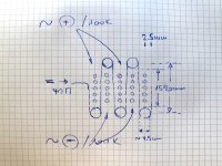
Thank you for your comments/feedback. In order to illustrate/answer you questions, I add another picture to better show some details of this construction. From this picture, you can see that the stretchers/spacers are 20mm apart. With a diameter of 4mm and the shrinked tube, this increases to some 4.3mm. This gives a free space of some 15mm between them for the membrane to swing. The stretchers hold the plexy baseplates at 70mm distance, so the membrane fitting beween them is some 65mm wide/high. With 7 spacers on each side, there is a total of 12 symmetrically driven membrane sections, and 2 asymetrically driven ones.
So each membrane section has an aera of some 15mm*65mm=9,75cm^2, the twelve symetrically driven sections add up to 114cm^2. Another two asymetrically driven membrane sections at each end of the array add up another 19.5cm^2.
As there are different sections, it is quite difficult to say something about "the fundamental membrane resonance". There are rather 14 distinct membrane sections, each one with it's own pecularities.
It is possible to drive this construct fullrange, but only at low levels. At higher input, soon the transformer cores saturate and get noisy at the rythm of the input, and potentially causing harm to the driving amplifier due to impedance loss. Also the membrane is more prone to sparking when driven with lower frequencies. So the measurements were made from 500Hz. When driven by a 4th Order LR-HP Filter @ 800hz ... 1kHz, then the sparking was seldom. From 1k2 on, no more sparking all with a music signal.
The bias resistors are 100k for the signal feed and 40M for the static HT.
Questions, questions, questions ...:
For a next prototype - what would you modify? Increase curtain depth, e.g. to 5cm (watch the higher frequency behavior)? Lowering the spacing to increase the sensitivity? This would also increase the witdh-to-depth ratio and narrowing the gap for the compressed air to flow, increasing distortion producst? Other Consequences? And another idea for the spacers: Would it be better to keep them hard, e.g. full V2A rods 5mm diam, or would it be better to make them more plastic/elastic, by taking a V2A with 3mm diam, and manteling it with a 3/5mm silicon tube? In order to let the membrane work along the countour of the spacers? Make the whole array bigger, higher, larger? Any other suggestions? Most welcome to comment!
Attachments
Last edited:
Good to see someone experimenting with an ES AMT rather than just commentating from the sidelines, leaving the work and risk taking to others.
Don't know if you have seen my thread from 2009 Electrostatic AMT?
ES AMT's with stators between the plates are the subjects of patents, but statorless designs maybe not. I use the word "maybe" because DTN Williamson of Williamson Amplifier fame described the dual polarity bias supplies needed long before Heil invented the AMT.
I think you should try reducing the spacing between the pleats to gain some sensitivity. Of course this will raise the depth/width ratio and further load what is already a weak motor.
If you have a read of the thread above you will find some excellent contributions from ESL experts such as David Janzen and Bolserst neither of whom are very optimistic about the viability of the ES AMT
Having said this I would seriously consider trying a more zig zag type of structure.
Keith
Thanks for the extra information. It makes the conversation more productive. I'm going to skip the discussion of the utility of AMT electrostatics and just focus on the electrostatic end of the design.
On spacing and output, another point of reference is the older Janszen midrange/tweeter panels (the square ones with the wire wrapped all the way around the plastic frames). Their diaphragm free area was roughly 11 mm by 110 mm (8 of these per panel), with around 0.3 mm diaphragm-to-stator spacing. They used a 1:72 audio step-up ratio and still needed 4 panels to achieve levels compatible with standard woofers (approximately 400 square cm of electrostatic total). The newer Janzen panels use a little more electrostatic area than this. Some of the older tweeter only designs used less area, but my main point here is that your current electrostatic area is small, so the low sensitivity is expected.
Maintaining accurate spacing at 0.3 mm is not something an average builder can handle though. Using 0.5 – 1 mm spacing is more reasonable. Cutting your current spacing in half will, at best, give you 6 dB more voltage sensitivity. To maintain electrostatic field uniformity with decreased spacing, the distance between conductors in your stator also needs to decrease to achieve the highest output.
On fundamental resonance: an undamped resonance is typically unpleasant on small panels. For best results, people typically apply some kind of damping to tame them or roll off the drive signal well before resonance. If you have an analog signal generator, a sine wave can be swept through the electrostatic's range to quickly highlight the membrane resonances. They'll be obvious even at moderate drive levels. It can help show you the unit's useful frequency limits.
I like working with small ESLs when I'm prototyping. It makes things go faster, and typically produces good enough information to make decisions before committing to a large build. If I were working on a project like this, I would also be comparing the output of the AMT design to that of a flat panel to determine how much benefit or detriment was being provided.
Where you go from here depends on what your goals are for the project, so I'm having a hard time suggesting a direction at the moment.
Last edited:
Thank you both for the input. If I build further on, I certainly will shrink the distances and enhance the membrane surface. Bur first I will have to do some reading: I am very sorry to say that I indeed searched the forum, using "AMT" and "electrostatic", along with the default option [search entire posts]. And I got a zillion of references ... So I did not find the needle in this haystack. I should instead have searched [search titles only] to have better chances to find the already existing thread covering this subject. And then I would of course have posted my input there, instead of opening a new and parallel thread. So I reinvented the wheel twice - once for the ESAMT, and twice for the thread ... Therefore, for the moment, there are two consequences for me: 1. I will study this other, already extensive thread first and the expert's input contained in it, first of all. 2. If after this learning by reading I build another proto, I will post some infos about it right into this other, 2009 dedicated "electrostatic AMT" tread. If someone thinks it could be useful to merge the initial infos of this thread to the existing one, then you are free to do so, and then let's cancel this thread.
This is Very Cool !!! 😀
I am glad to see that someone has finally been able to take the time to try this method. 🙂
Cheers !!

Jer 🙂
I am glad to see that someone has finally been able to take the time to try this method. 🙂
Cheers !!
Jer 🙂
Thanks for the cudos.
Cool? Maybe. It is also a proof of diligent ignorance ... Had I found and also read the correct thread before, and especially bolserst's and also D.Janzen's posts ... then I would never had started this useless construction. Meanwhile, knowing more about the theory by now, I know that this proto belongs into the category "why keep things simple - if you also can archieve the same in a more complicated way".
But it was certainly fun to build it. And it also has the optical charme of a vintage RR-frontcooler inlet. Less the top/roof triangle of the doric temple.
So definitively, there certainly will be no proto MK II.
Since you will have a force cancellation you can go with a very thin steel plate instead of rods.
0,35mm steel would work, maybe even 0,3mm.
0,35mm steel would work, maybe even 0,3mm.
Daihedz, Ya , I never did follow through with it because it was so labor intensive to get enough panels together with enough displacement to make a difference on the low end.
Dynamic drivers are best suited for that IMHO. 😉
jer 🙂
Dynamic drivers are best suited for that IMHO. 😉
jer 🙂
Well, very nice build despite it did not work out YET as you hoped for.
Very clever design of your multiplier, like that.
Although it has crossed my mind too ESL-AMT, I start building a normal ESP first but I need to get a more little knowledge about it. Things like how does the surface area effect the driving force? IOW will it make much of a difference if you add more stator rods or even use a closed plate?
Any pointers about Transformers to use/obtain are appreciated.
- Home
- Loudspeakers
- Planars & Exotics
- An unusual electrostatic AMT DIY approach - an attempt, at least ...