I had this idea around 1975.
....
Sorry, i leave this forum, so if you are interested in this circuit, please, consult my web site.
....
Sorry, i leave this forum, so if you are interested in this circuit, please, consult my web site.
Attachments
Last edited:
Apart the fact that it detect all kind of problems, reason why i call-it ultimate, this idea brings a big advantage.
It fire the protection quasi instant (µs), with not the additional long delay needed by the integrator stages that usual protection circuits use, by habit, to detect DC.
Instant even in case of short circuit, and before your powe amp devices suffer. For the same reason, it can protect your fragile tweeters against very low DC levels.
This thread is opened to be a cooperative one; All of you who want to collaborate, bring ameliorations, printed board designs, experience returns etc... are highly welcomed.
Hope it will help some of you, folks
Such an idea (comparator) can be applied using the amps own internal error correction port, as well. amplify and rectify it and drive relay/disconnect.
Separate relay drivers for left and right channels might allow the amp to finish a gig/concert with degraded sound - one channel.
Some amps, like the CS800s and PV 1.3k amps I am working on, have variable gain to allow for different inputs. The detection circuit couldn't cope with that without modification.
Relay drive circuit currents, and signal ground return currents, should be separated for less noise at end of power up reset. I prescribe an opto isolator or a coupling transformer for AC relays.
You are right, mr Marsh, of course. (Thanks for your interest).Such an idea (comparator) can be applied using the amps own internal error correction port, as well. amplify and rectify it and drive relay/disconnect.
Of course i had tough to that.
The major advantage would be we do not need to tune any level to compensate the gain factor of the amp.
There are several reasons why i chosed my solution.
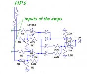
- The virtual point where the two signals (input and feedback) are mixed together in the amp is very sensitive to any parasitic cap. (Like in the bus of a mixing console). Cabling a wire there to go to the protection board can deteriorate the amp performance or stability. Specially if your amp goes up to several Mhz.
- To find this point can be difficult for people with little electronic understanding.
- We loose the protection against DC in the input, as long as the amp can amplify-it before clipping.
-The last reason is, as i mentioned-it, i wanted this circuit to fit any existing amp, without any internal modification.
On a new amp project, it would be easy to add a single transistor, like an emitter follower directly on the board, to isolate the amp from any influence of this cable, saving the op Amp comparators. But, again, we lose the DC protection of the input. It would be OK for an input cap protected amp.
I just use a simple PIC micro to monitor the output voltage.
If it goes above/below 20 volts for greater than 500ms it immediately shuts down the output relay.
If it goes above/below 20 volts for greater than 500ms it immediately shuts down the output relay.
Last edited:
As the circuit is unique for the two channels, it will cut the 2 channels in the same time. You are right. Better for an home amp. Easy to separate in two, if you prefer.Separate relay drivers for left and right channels might allow the amp to finish a gig/concert with degraded sound - one channel.
Relay drive circuit currents, and signal ground return currents, should be separated for less noise at end of power up reset. I prescribe an opto isolator or a coupling transformer for AC relays.
I used this idea when i was at the head of a big PA system rental company (Audio Analysts) and it had saved our life's amps several time with no negative effects. We used more than one amp for each way (sub bass, bass, middle, high middle, treble etc) so it was not a big problem.
I have to said that, each time the protection fired, the problem was so important that it was no way to continue the show (Orage with huge water fall in the Altec horns, cut of the HP cables before the show etc...)
Of course, for PA, you have to set the protection with enough margin that it will not fire at the littlest clipping.
About powering of the relays, this circuit is powered by a separate power supply from the amp, and has just a ground floating point in common with the amp itself. (no current).
In my home amp, there is never the slightest clic, whatever you do, from power on to power off, and even when you fire the protection at any level.
You can adjust this protection to fire in < 0.1ms if any DC as low as 100mv.If it goes above/below 20 volts for greater than 500ms it immediately shuts down the output relay.
How can your Pic detect amp HF oscillations dangerous for your tweeters ?
I would like to add that this protection can detect any amp clipping and fire at the first kick drum, depending of the margin you set. Tune-it according to your needs.
May ask you, please, to do not comment endless the "so calling" inconvenience of the serial relay or/and paralleled solid state switch and it supposed sonic degradation.
(I'm unable to hear the difference with a wire in my high end system)
You are free to use this idea to any other solution (power supply rails cut, direct action inside a regulated power supply etc...) if you believe that it is better.
Just remember that, if any big cap after the relays in the rails, they will continue to discharge in your speakers if any power device short circuit, after protection had fired. Chose your poison.
This solution has been chosen to be 'universal' and able to be adapted outside an existing amp with no mod.
Last edited:
I hope to that some DIYer here, faster than me at this game, will be interested to design and propose some nice PCBs....greetings any pcb for this project to share.
Hi Esperado,
Nice circuit, I have been thinking something like this quiet a while ago but can't make any circuit drawing like you do... 🙁
I'm also thinking to use transformer current sensing somewhere (maybe at the mains input) added to the circuit, of course if it is necessary.
For the comparator can we use another op amps e.g. TL072, or another that can easily available? Or what type op amps that should be use there...
Regards
As the comparator is supposed to subtract one signal to the other, it is obvious that any phase difference introduced by the Op amp will create errors. Reason why you need a very fast Op amp. But, if your power amp itself is not ultra fast, he will create some phase rotation at HF by itself. So, the difference will not be a big issue.For the comparator can we use another op amps e.g. TL072
In my home amp (ultra fast), i used TL074 op amps, with an little increased security margin before protection fires, and it works good enough since decades.
About transformer sensing, nothing to be found this side, i believe: The big caps power reserve of your power supply will destroy your loudspeakers before you can sense any big change near the sector. It is just good to evaluate average power consumption, where we need fast peak sensing..
Last edited:
Hi Esperado
greetings this is what i have been looking for i will try to design pcb for this project can you give part no of
1 solid state mosfet relays
2 optoisolators
used in this project hoping i can collect all parts for this project
warm regards
andrew lebon
greetings this is what i have been looking for i will try to design pcb for this project can you give part no of
1 solid state mosfet relays
2 optoisolators
used in this project hoping i can collect all parts for this project
warm regards
andrew lebon
I greatly appreciate your proposal and we will all be thankful. Please, give-me some hours to find easy available parts for those.i will try to design pcb for this project can you give part no of
1 solid state mosfet relays
2 optoisolators
used in this project hoping i can collect all parts for this project
Hi Esperado
greetings thanks for replying i am no pcb expert but i will try my hardest to
make the pcb please take your time try to incoporate easy to find parts so diyers can make it
warm regards
andrew lebon
greetings thanks for replying i am no pcb expert but i will try my hardest to
make the pcb please take your time try to incoporate easy to find parts so diyers can make it
warm regards
andrew lebon
Thanks Esperado for the explanation,About transformer sensing, nothing to be found this side, i believe: The big caps power reserve of your power supply will destroy your loudspeakers before you can sense any big change near the sector. It is just good to evaluate average power consumption, where we need fast peak sensing..
I see 😎 that why I never see current sensing trafo use as protection in power amps. We need something fast enough here, I have TL074 will use it if can't find faster op amps.
And so for the solid state mosfet relay here used because it is faster than ordinary relay...
Regards
In fact, the mechanical relay is fast enough.And so for the solid state mosfet relay here used because it is faster than ordinary relay...
The mosfet is paralleled here for two reasons. he will continue to pass the signal, even if the mechanical relay is oxidized and it reduce serial impedance.
More than that, when the relay is set in his passing state, it often produce some rebound -> sparks. Here, because there is very little current anyway (the Mosfet is yet conducting) it helps to prevent that.
One thing the mosfet don't do, is to help when protection fire. As the MOSFET will cut himself faster, you have all the chances that the mechanical relay has to break the amps alone. We can improve this behavior, adding some delay to the MOSFET to operate. But it will add a delay when the protection fire, and can be difficult to tune according to the relay's speed disparities.
All that is very rhetorical. In normal operations, the relay will goes on and off with no signal or DC, and difficult situations (short circuit in HP lines) are rare enough, if the relay is strong enough, to do not change his life durability.
I had made hundred of demonstrations, more than 10 years ago, short circuits at full power my 140W amp, and everything is still healthy, relay included. And i have no parallel MOS in my personnal Amp.
Last edited:
I have to add that, in normal operation, or short circuit, as the input signal in shorted to 0 by a faster switch before the mechanical relay opens, this relay will never have to deal with currents. This will only happens if the amp is burned and output at rail level. In this situation, you will not care about the suffering of your relay: Your amp is out of order, and your loudspeakers are safe. Goal.
What do you think about this PS regulator integrated with the speaker protection and short circuit protection. http://www.diyaudio.com/forums/powe...iplier-electronic-protection.html#post2901733
I use it with my TT amp and it works quite good, ones prototected my speaker after an error in the amp.
dado
I use it with my TT amp and it works quite good, ones prototected my speaker after an error in the amp.
dado
- Home
- Amplifiers
- Solid State
- An ultimate amp protection circuit ?