I'd like to present a design for a power amplifier, the main features of which are as follows:
The principle on which the design is based is that of a current (high-impedance) amplifier, using feedback to reduce the output impedance.
Full details, including a practical design example, can be found at: https://robinet.co.uk/amplifier-design.
I have attached RTA spectra plots taken using REW, showing the performance of this design at 1 Watt into 8 Ohms, and at 100 Watts into 4 Ohms.
Comments will be welcome.


- The output impedance can be varied from a fraction of an Ohm, to several Kilo-ohms, by selecting two resistors.
- The amplifier is stable with virtually any load.
- It is very robust, and can survive accidental short-circuits.
- Total harmonic distortion is below 0.02% at 1 watt into 8 Ohms, up to 40kHz (This is a real measurement, not a simulation).
The principle on which the design is based is that of a current (high-impedance) amplifier, using feedback to reduce the output impedance.
Full details, including a practical design example, can be found at: https://robinet.co.uk/amplifier-design.
I have attached RTA spectra plots taken using REW, showing the performance of this design at 1 Watt into 8 Ohms, and at 100 Watts into 4 Ohms.
Comments will be welcome.

t's nice to see something different around here, for a moment I thought you were describing my amp.
Very nice and a different approach to amplification.
And a triple Sziklai as an output stage - daring!
Work for serious study.
And a triple Sziklai as an output stage - daring!
Work for serious study.
Congratulations! While there's a bunch of us who tackled this class b current mirror drive output mainly through voltage feedback, it's not the overall current feedback that draw my attention. I have to say it didn't cross my mind using that secondary shunt current feedback path through the
current mirror to controll the output impedance through the power transfer ,but then I remembered Marcel VDG design from 1996 which looks like using the same concept with a mosfet output : https://www.diyaudio.com/community/threads/margan-non-switching-class-b.122007/page-3#post-6999038
current mirror to controll the output impedance through the power transfer ,but then I remembered Marcel VDG design from 1996 which looks like using the same concept with a mosfet output : https://www.diyaudio.com/community/threads/margan-non-switching-class-b.122007/page-3#post-6999038
Attachments
Excellent. I heard 2 of Duo’s trans amps , one based on a diskrete electron gun and one based on LM3875. They had a bit more Rout range and are continues range set by a potThe output impedance can be varied from a fraction of an Ohm, to several Kilo-ohms
Very good sonics, every loudspeaker best with a different setting
dave
You may need to constantly controll the output impedance in a current conveyor output as you always know the voltage drive , the current drive being the unknown, so I'd say it's a topology dependent type of controll which in a well known emitter follower design still goes down to making the output being seen as purely resistive as the distortions are related to a voltage function instead of a current function so a classical voltage feedback still does what it needs to do if it can monitor all the voltage variations .
Reading a purely resistive output can be done both in a classical way or as in KCP current feedback way where the load impedance is controlled with a voltage function within a classical emitter follower topology and the double current feedback is used to null the current variations
https://www.edn.com/the-class-i-low-distortion-audio-output-stage-part-2/
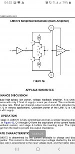
If we're looking into a very high slew rate feedback design as in LM6172 we see it's a voltage controlling the current nonlinearities of the drive and output stage while preserving the pure voltage drive develloped over the input Re, but that Re is purely conceptual , it's actually the final stage Re that's deemed to be maintained in a pure resistive form with the aid of a classical VFB.
Do we still have a case for high slew rates amplifiers in VFB designs if we can convert the output current over output impedance into pure voltage feedback?
Reading a purely resistive output can be done both in a classical way or as in KCP current feedback way where the load impedance is controlled with a voltage function within a classical emitter follower topology and the double current feedback is used to null the current variations
https://www.edn.com/the-class-i-low-distortion-audio-output-stage-part-2/
If we're looking into a very high slew rate feedback design as in LM6172 we see it's a voltage controlling the current nonlinearities of the drive and output stage while preserving the pure voltage drive develloped over the input Re, but that Re is purely conceptual , it's actually the final stage Re that's deemed to be maintained in a pure resistive form with the aid of a classical VFB.
Do we still have a case for high slew rates amplifiers in VFB designs if we can convert the output current over output impedance into pure voltage feedback?
Attachments
Last edited:
Well...I know Sziklay output pairs behave better on low output loads and there's ton of proof on that, so I'm not trying to get a forced equality between different topologies, I quite like the OP's design, I just anxiously wait to have my arguments completely destroyed by people more knowledgeable than me 🙂
Very good sonics, every loudspeaker best with a different setting
Aren't you then basically -artificially- boosting bass, making up for speaker LF imperfections? Same could be achieved with a proper LF equalizer i.m.o..
Sorta, sometimes. More taking advantage of the current drive & the loudspeakers impedance to extend up & down.
For instance the FExx6 horns this is baked in so one can be married with a highish Rout SET.
dave
For instance the FExx6 horns this is baked in so one can be married with a highish Rout SET.
dave
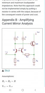
It would appear that an error crept into my published schematic. If anyone built (or simulated) it, it would not have worked as intended, possibly not at all. The error concerns the connections to Q3. So, here, with my apologies, is the correct schematic.
John.
John.
Attachments
I posted this a while back. Copy the comments to a csv spread sheet to find resistor values for other gain and/or output impedance. Select values for the desired gain (A=23.5), the sense resistor (R=0.39), the output impedance (Z=4) and resistors Pa (=10K) and Na (=10K).

Attachments

Thread split of Kendall Castor-Perry's Class I output stage is now here:
https://www.diyaudio.com/community/...rys-class-i-output-stage.427174/#post-8000899
- Home
- Amplifiers
- Solid State
- Amplifier with Predictable Output Impedance