Friends, I found a 0dB amplifier circuit diagram on the Internet.
How about this schematic diagram? Can it be directly applied

How about this schematic diagram? Can it be directly applied
Some aspects of the design look odd tbh. That's not to say it won't work but it raises questions.
What does the 1 meg do beside couple noise from the PSU into the input. Maybe the thinking is to apply a polarising voltage to the two caps. Not great design imo. You could use a bipolar cap if needed.
Why include gate stopper resistors (normally done to aid stability) and then bypass them with small value caps which seems to defeat their purpose.
The 0.1uF across the two drivers only looks as though it would worsen distortion because the signals at these two points are totally different to each other. Why connect them together?
Outputs rarely need the same gate stopper resistor. Look at the component data sheets.
No global feedback would tend to higher distortion
One can use better input caps and dispense with the DC cap bias
I have never seen a practical reason for two power supplies. So what if the output does not quite swing to the rails? Actually an advantage is more coulombs in the power supply caps with the one higher voltage.
In other words, lots of circuits on the internet. Some very good. Some not. Always toss the model into Spice to see how it behaves.
Zero gain? What would this be used for?
I don't know why the designer added a 1m ohm resistor in the middle of the input capacitor and connected it to the power supply.
0dB, without big loop feedback, the sound quality should be good
Thank you for your reply
0dB, without big loop feedback, the sound quality should be good
Thank you for your reply
Some aspects of the design look odd tbh. That's not to say it won't work but it raises questions.
What does the 1 meg do beside couple noise from the PSU into the input. Maybe the thinking is to apply a polarising voltage to the two caps. Not great design imo. You could use a bipolar cap if needed.
Why include gate stopper resistors (normally done to aid stability) and then bypass them with small value caps which seems to defeat their purpose.
The 0.1uF across the two drivers only looks as though it would worsen distortion because the signals at these two points are totally different to each other. Why connect them together?
Use it as a pure post amplifierOutputs rarely need the same gate stopper resistor. Look at the component data sheets.
No global feedback would tend to higher distortion
One can use better input caps and dispense with the DC cap bias
I have never seen a practical reason for two power supplies. So what if the output does not quite swing to the rails? Actually an advantage is more coulombs in the power supply caps with the one higher voltage.
In other words, lots of circuits on the internet. Some very good. Some not. Always toss the model into Spice to see how it behaves.
Zero gain? What would this be used for?
Its characteristic is to get rid of large loop feedback
So, you need a input with a 30V swing? Where are you getting that? Again, what purpose does this amp serve? Not even for headphones. Not a line buffer.
Why do you believe no feedback sounds good? Do not fall for slick page reviewer nonsense. Distortion does not sound good.
Input is to bias the electrolytics to reduce distortion. Trivial compared to the rest of the circuit and needless as much better film caps are available that do not need such bias. Actually, if you read up on it, just using one large electrolytic pretty much eliminates the issue anyway. A 2uF film is even better eliminating the DC bias hack.
Circuit is without a decent input RF filter. Questionable if the high current driver stage is of any benefit. The .1 Ohm resistors are not needed, but maybe shown as parasitic resistances. Do a proper Bode plot and see what all those .1u caps are really doing. Simulation can give you an idea for the range of the "*" resistor for the spreader. Then consider Mr. Pass's views on the first few Watts vs others on smaller class A regions but better feedback architecture as how they deal with crossover distortion and thermal drift.
If you are diving into amplifier design, might I suggest reading Cordell and Self. Read the various papers from our favorite forum contributors, Pass and Didden etc. Even the little MOSFET amps from Ron Elliot are well thought out even if quite simple. Go find the old Audio Amateur series E.B. did on a MOSFET amp and follow the evolution. There are some very good articles in Jan's annual Linear Audio worth reading. Technical by real engineers. Know where you are getting your advice.
I am sure Mooly can point you to other contributors who are real engineers with real experience. Search the internet for schematics of well respected amplifiers and study them. Put them into Spice and see how they behave. Play with them seeing how swapping local for global feedback changes the ratio of even vs odd harmonic distortion. See the effects of various constant current sources. Read up on why some folks advocate FET input stages. Understand the differences in linearity between FETs and BJTs and what effect feedback has on them. Understand what differences load impedance has on the amplifier. Understand the relationship between input impedance and noise.
Yea, it is complicated.
So, you need a input with a 30V swing? Where are you getting that? Again, what purpose does this amp serve? Not even for headphones. Not a line buffer.
Why do you believe no feedback sounds good? Do not fall for slick page reviewer nonsense. Distortion does not sound good.
Input is to bias the electrolytics to reduce distortion. Trivial compared to the rest of the circuit and needless as much better film caps are available that do not need such bias. Actually, if you read up on it, just using one large electrolytic pretty much eliminates the issue anyway. A 2uF film is even better eliminating the DC bias hack.
Circuit is without a decent input RF filter. Questionable if the high current driver stage is of any benefit. The .1 Ohm resistors are not needed, but maybe shown as parasitic resistances. Do a proper Bode plot and see what all those .1u caps are really doing. Simulation can give you an idea for the range of the "*" resistor for the spreader. Then consider Mr. Pass's views on the first few Watts vs others on smaller class A regions but better feedback architecture as how they deal with crossover distortion and thermal drift.
If you are diving into amplifier design, might I suggest reading Cordell and Self. Read the various papers from our favorite forum contributors, Pass and Didden etc. Even the little MOSFET amps from Ron Elliot are well thought out even if quite simple. Go find the old Audio Amateur series E.B. did on a MOSFET amp and follow the evolution. There are some very good articles in Jan's annual Linear Audio worth reading. Technical by real engineers. Know where you are getting your advice.
I am sure Mooly can point you to other contributors who are real engineers with real experience. Search the internet for schematics of well respected amplifiers and study them. Put them into Spice and see how they behave. Play with them seeing how swapping local for global feedback changes the ratio of even vs odd harmonic distortion. See the effects of various constant current sources. Read up on why some folks advocate FET input stages. Understand the differences in linearity between FETs and BJTs and what effect feedback has on them. Understand what differences load impedance has on the amplifier. Understand the relationship between input impedance and noise.
Yea, it is complicated.
I did get some hype about feedback amplifiers without large loops
I really like it here, because I can always meet friends who can give me professional advice! Thank you.
My English is so poor. It's hard for me to read those academic papers. I benefited a lot from your help~~
Poor man's bipolar electrolytic - however the input needs a bleed resistor to ground, perhaps 47k, otherwise plugging a cable in will make the loudest thump you can imagine!! Its a 1M resistor, not 1m, note.I don't know why the designer added a 1m ohm resistor in the middle of the input capacitor and connected it to the power supply.
Nice to meet you,Poor man's bipolar electrolytic - however the input needs a bleed resistor to ground, perhaps 47k, otherwise plugging a cable in will make the loudest thump you can imagine!! Its a 1M resistor, not 1m, note.
You're right. It also needs a discharge resistor
Even better to remove the 1M resistor and both electrolytics. Then use a single 2uF film. Or do the math and provide a little subsonic filter with an even smaller cap.
10K input impedance seems a bit low. Maybe chosen for noise?
I still do not see any use case. Is this being fed by a high gain tube preamp? In other words, just a high current output stage?
10K input impedance seems a bit low. Maybe chosen for noise?
I still do not see any use case. Is this being fed by a high gain tube preamp? In other words, just a high current output stage?
It seems to me that the circuit assumes the output devices 2SJ554 and 2SK2955 are matched to each other, since they have identical 100 ohm gate bias resistors and identical 0.1 ohm source degeneration resistors. If those MOSFETs are mismatched, especially if their |VGS_threshold| values are significantly different, then the OPS becomes unbalanced. Probably grossly unbalanced.

WEIRD!!!
Lots of poor/iffy choices
And the unusual DC biasing applied just to use large electrolytics there.
And the guaranteed ripple injection straight to the input.
and ... and ... and ....
Run away!!!!!
Lots of poor/iffy choices
Friends, I found a 0dB amplifier circuit diagram on the Internet.
How about this schematic diagram? Can it be directly applied
View attachment 1041166
And the unusual DC biasing applied just to use large electrolytics there.
And the guaranteed ripple injection straight to the input.
and ... and ... and ....
Run away!!!!!
Thanx for posting something interesting. The word that comes to mind is "pointless", like bypassing the gate stopper resistors, and using an 800 V 2SK2955 as a compliment a 60V 2SJ554; on a 70V supply, and the fact that neither of these is a commonly available part. Perhaps there is a subtle reason that is not obvious? The output circuit is a CFP / Sziklai topology which means it uses local feedback. That means it has less distortion than a simple follower, but it does use feedback. But mostly the input circuit is counterproductive. The boosted +/-40V supply is only useful to make the CCS bias work, which is pointless to begin with. The bias voltage to make 100uF input caps bipolar is similar since the high input impedance of FETs will pass any useful audio frequency with a much smaller (and bipolar) capacitor, like maybe 1uF. Of course, DIYA is full of such things. You have the right to waste your time and money however you like.
LOOK AGAIN 😉since the high input impedance of FETs will pass any useful audio frequency with a much smaller (and bipolar) capacitor, like maybe 1uF.
Input signal goes straight to very bipolar 2SC1815/2SA1015 and to boot, wired as common base amps.
Not wasting time in calculating it, but input impedance, with good luck, might hover around 1K or so ... if not lower.
Make your own minds up...
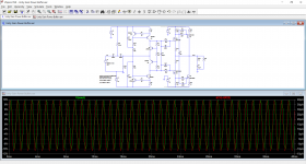
Check for any obvious mistakes I might have made but it seems to make a good attenuator. Notice Vin vs Vout.
Super critical on setting the DC offset, a tenth of an ohm in the 100 ohm preset makes a massive difference.
Distortion hugely dependent on bias current as expected. Set at 350ma here.


Check for any obvious mistakes I might have made but it seems to make a good attenuator. Notice Vin vs Vout.
Super critical on setting the DC offset, a tenth of an ohm in the 100 ohm preset makes a massive difference.
Distortion hugely dependent on bias current as expected. Set at 350ma here.
Attachments
As a pure post amplifier with 0dB voltage gain, the input impedance is indeed very lowLOOK AGAIN 😉
Input signal goes straight to very bipolar 2SC1815/2SA1015 and to boot, wired as common base amps.
Not wasting time in calculating it, but input impedance, with good luck, might hover around 1K or so ... if not lower.
Thank you, dear moolyMake your own minds up...
Check for any obvious mistakes I might have made but it seems to make a good attenuator. Notice Vin vs Vout.
Super critical on setting the DC offset, a tenth of an ohm in the 100 ohm preset makes a massive difference.
Distortion hugely dependent on bias current as expected. Set at 350ma here.
View attachment 1041461
View attachment 1041462
Your simulation test is of great reference value. I decided to make some improvements to this circuit. Hope to get good results
Your welcome 🙂Thank you, dear mooly
Your simulation test is of great reference value. I decided to make some improvements to this circuit. Hope to get good results
And with opamp front end.
Attachments
The 220µ bypass cap is wrongly connected.Make your own minds up...
Check for any obvious mistakes I might have made but it seems to make a good attenuator. Notice Vin vs Vout.
The circuit is actually a unity gain buffer, and its input impedance is ~250K (without taking the 10K into account).
The cap across the gates greatly improves the symetry, and therefore the linearity, but it needs to be much larger, and it would make the amplifier super-sensitive to power supply noise.
All the remarks made by other members also apply, of course
Attachments
- Home
- Amplifiers
- Solid State
- Amplifier drawings that look good