I have an amp that appears to have a separate audio ground for the unbalanced input. The PSU, output boards and -ve speakers are grounded to the main star but the input boards has its own separate ground for the unbalanced input which eventually connects to the main ground via a ground wire to the output boards. The balanced ground connects to the chassis but not at the star point. The amp suffers from ground loop hum on the unbalanced input. My thinking is that if I connect the balanced ground to the unbalanced on the input boards and then rewire the balanced ground to the star point, that may go some way to alleviate my hum issue. Is this correct? I have read this site's article on grounding, btw, which has given me the idea of connecting grounds to a common point.
Any thoughts on this? What would be the point of separating the balanced and unbalanced grounds and not star grounding the unbalanced input immediately?
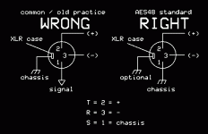
The balanced pin1 is not an audio ground. It is a low resistance that couples the chassis together. This low resistance path allows leakage currents and mains earth currents to pass between equipment without causing Audio Hum.
I do not think it a good idea to move the non-audio currents to the unbalanced ground reference point.
I do not think it a good idea to move the non-audio currents to the unbalanced ground reference point.
The balanced pin1 is not an audio ground. It is a low resistance that couples the chassis together. This low resistance path allows leakage currents and mains earth currents to pass between equipment without causing Audio Hum.
I do not think it a good idea to move the non-audio currents to the unbalanced ground reference point.
thanks for the reply. On this amp, the chassis also acts as the point to which the star ground for PS, output boards and -ve speaker are attached. If I maintain Pin 1 separation and keep it attached to the chassis at the nearest point, my next best option then is to take the unbalnced shield at point of entry and provide an immediate connection to the star ground ala the reference article. At the moment, the unbalanced ground goes "round the houses" to get to the star ground.

thanks for the reply. On this amp, the chassis also acts as the point to which the star ground for PS, output boards and -ve speaker are attached. If I maintain Pin 1 separation and keep it attached to the chassis at the nearest point, my next best option then is to take the unbalnced shield at point of entry and provide an immediate connection to the star ground ala the reference article. At the moment, the unbalanced ground goes "round the houses" to get to the star ground.
Whatever you do, keep the balanced input pin 1 connected to the chassis at the nearest point. Connecting it to signal reference is/was a commonly made mistake known as the "pin 1 problem".
I'm assuming the amp has been designed in such a way that an internal groundloop is impossible (abiding one of the "laws" in the article you refer to).
Connecting the unbalanced shield via the shortest route to the star ground instead of having it travel all over the place first might help a little, but... if the cause of the groundloop is outside the amp, this will not cure the problem.
The way to find out is to disconnect every source and reconnect one by one until the groundloop occurs. Once you've identified the culprit, try to find out why it contributes to the groundloop and what you can do about it.
I once had a huge groundloop between my pc and my amp. On the one side there was the amp connected to a tuner that itself was earthed by the shield of the central antenna system (all class II aplliances that weren't connected to safety earth). On the other side was the PC that was connected to safety earth. Since this was in the attic, the surface of the groundloop was huge and the hum loud. I didn't want to disconnect the PC from safety earth so I had to break the groundloop with audio transformers in the analogue circuit. Later I broke it using a coax to optical converter in the SPDIF signal.
Attachments
Last edited:
It seems like the unbalanced signal input's ground conductor should follow the signal conductor closely (to make minimal enclosed loop area) and tie to ground only at the grounded end of the input resistor at the first actual amp input stage, and the input resistor's ground reference should have a separate conductor to the main star ground.
Thanks. There is hum from various sources on the unbalanced line but no hum from an unconnected input (not PS ripple hum). I have been using a ground loop cable with a small isolation transformer for now. I suspect the problem is in the sources but just wanted to be absolutely positive. I'll leave the pin 1 ground as it is as I rarely us the balanced line anyway.Whatever you do, keep the balanced input pin 1 connected to the chassis at the nearest point. Connecting it to signal reference is/was a commonly made mistake known as the "pin 1 problem".
I'm assuming the amp has been designed in such a way that an internal groundloop is impossible (abiding one of the "laws" in the article you refer to).
Connecting the unbalanced shield via the shortest route to the star ground instead of having it travel all over the place first might help a little, but... if the cause of the groundloop is outside the amp, this will not cure the problem.
The way to find out is to disconnect every source and reconnect one by one until the groundloop occurs. Once you've identified the culprit, try to find out why it contributes to the groundloop and what you can do about it.
I once had a huge groundloop between my pc and my amp. On the one side there was the amp connected to a tuner that itself was earthed by the shield of the central antenna system (all class II aplliances that weren't connected to safety earth). On the other side was the PC that was connected to safety earth. Since this was in the attic, the surface of the groundloop was huge and the hum loud. I didn't want to disconnect the PC from safety earth so I had to break the groundloop with audio transformers in the analogue circuit. Later I broke it using a coax to optical converter in the SPDIF signal.
It seems like the unbalanced signal input's ground conductor should follow the signal conductor closely (to make minimal enclosed loop area) and tie to ground only at the grounded end of the input resistor at the first actual amp input stage, and the input resistor's ground reference should have a separate conductor to the main star ground.
I'll add a grounding wire to star at the input resistor's ground for good measure. Thanks for all the help everyone.
Thanks. There is hum from various sources on the unbalanced line but no hum from an unconnected input (not PS ripple hum). I have been using a ground loop cable with a small isolation transformer for now. I suspect the problem is in the sources but just wanted to be absolutely positive. I'll leave the pin 1 ground as it is as I rarely us the balanced line anyway.
I'll add a grounding wire to star at the input resistor's ground for good measure. Thanks for all the help everyone.
If there is hum with inputs connected but no hum with inputs unconnected, then it could be that there is loop area enclosed by separated signal input and input ground conductors, because without an input connected (or a resistor or short across an input) there is no loop. But with a source connected, the current induced in the loop would induce a voltage across either the input resistor or the source impedance (and a tiny bit across the distributed impedance of the conductors).
So I would try it with the unbalanced inputs shorted or with a resistor across each one, to possibly rule out the source equipment.
If there is still hum, then it might be loop area being formed by the input signal and ground paths being physically separated.
The only way I know to be sure they're not is to make sure that the input jack is isolated from the chassis and any other ground, and run the signal and ground conductors as close together as possible all the way to the first actual amp input point, which is usually a resistor to ground, with the signal conductor to the ungrounded end and the ground conductor to the grounded end, which then has its own separate conductor to the main star ground.
A good way to wire the signal and ground from the input jack to the input resistor is probably using shielded twisted pair, with the signal and signal ground on the twisted pair and the shield NOT connected to signal ground, but rather only to chassis ground on the end where the input jack is, with the shield unconnected on the end where the input resistor is. The perfectionist would run the wire from the twisted pair that is carrying the signal ground right along the input resistor leads and body, to its ground end.
If you do run an extra star ground wire to the input resistor, make sure that it is the ONLY ground connection for that resistor, and for the signal input's ground conductor.
Cheers,
Tom
Last edited:
If there is hum with inputs connected but no hum with inputs unconnected, then it could be that there is loop area enclosed by separated signal input and input ground conductors, because without an input connected (or a resistor or short across an input) there is no loop. But with a source connected, the current induced in the loop would induce a voltage across either the input resistor or the source impedance (and a tiny bit across the distributed impedance of the conductors).
So I would try it with the unbalanced inputs shorted or with a resistor across each one, to possibly rule out the source equipment.
If there is still hum, then it might be loop area being formed by the input signal and ground paths being physically separated.
The only way I know to be sure they're not is to make sure that the input jack is isolated from the chassis and any other ground, and run the signal and ground conductors as close together as possible all the way to the first actual amp input point, which is usually a resistor to ground, with the signal conductor to the ungrounded end and the ground conductor to the grounded end, which then has its own separate conductor to the main star ground.
A good way to wire the signal and ground from the input jack to the input resistor is probably using shielded twisted pair, with the signal and signal ground on the twisted pair and the shield NOT connected to signal ground, but rather only to chassis ground on the end where the input jack is, with the shield unconnected on the end where the input resistor is. The perfectionist would run the wire from the twisted pair that is carrying the signal ground right along the input resistor leads and body, to its ground end.
I'll try that but at the moment the amp is in pieces so when I get it back together, I'll test things out. The only caveat is that the input jacks (for both balanced and unbalanced) are actually mounted on the PCB of the input boards so the input resistor sits "right there" at the jack. From this point, the ground goes to the star ground via two routes. The first is the ground of the power connector to the input board coming from the PSU. This is from the low voltage side of the PSU but that is connected to the main supply ground through the PSU ground plane. The second is via the twisted pair ground/signal wire going to the output board which then connects to the PSU's main ground via the power connector to the board. It seems to me that the input resistor is one of the furthest ground locations from the main star as you could get so that might be a place to start. I can always snip the wire if it does more harm than good. I also found that the RF shunt ceramic cap in the input (just before the input resistor) was damaged and giving erratic readings (i.e. showing thermally-affected DC leakage). This most certainly would not have helped. 🙄
I'll try that but at the moment the amp is in pieces so when I get it back together, I'll test things out. The only caveat is that the input jacks (for both balanced and unbalanced) are actually mounted on the PCB of the input boards so the input resistor sits "right there" at the jack. From this point, the ground goes to the star ground via two routes. The first is the ground of the power connector to the input board coming from the PSU. This is from the low voltage side of the PSU but that is connected to the main supply ground through the PSU ground plane. The second is via the twisted pair ground/signal wire going to the output board which then connects to the PSU's main ground via the power connector to the board. It seems to me that the input resistor is one of the furthest ground locations from the main star as you could get so that might be a place to start. I can always snip the wire if it does more harm than good. I also found that the RF shunt ceramic cap in the input (just before the input resistor) was damaged and giving erratic readings (i.e. showing thermally-affected DC leakage). This most certainly would not have helped. 🙄
It could work much better to run a proper star ground for the unbalanced input signal ground. BUT, IF YOU DO run a new star ground conductor for it, then you SHOULD disconnect it from both of the other ground paths, completely.
The grounding scheme of your amp sounds pretty strange. And I am not sure if the balanced and unbalanced are done separately, or how they are done. A diagram would probably help tremendously.
Star grounding MEANS not sharing signal reference ground return conductors with power ground-return conductors, for example.
One of the main ideas is: Any currents in a ground return conductor induce voltages back at the non-star-ground end of the conductor. Any voltage induced at a signal input resistor reference ground point will ARITHMETICALLY SUM with your signal input voltage! Get the picture?
I imagine that the output board is having the same problem, if its ground returns all run back through a common power ground conductor (not to mention also running the input signal ground through there!).
Usually speaker grounds should run completely separately from everything else, back to the star ground.
And certainly anywhere a signal goes into an amplification component, where there's usually a resistor to ground from an input pin, then that resistor's ground return conductor should usually go back to the main star ground all by itself, but certainly should not share any length of conductor with any other ground-return current that is either highly-dynamic (fast-changing) or high amplitude.
If there's a real ground plane layer, that can make it unnecessary to worry as much about completely separate ground returns. So, your mileage may vary. But for diagnosing where hum is coming from, all of those ideas should still be considered.
But also keep in mind that there are two separate things we are worrying about: 1) not sharing ground-return conductors (especially for signal input ground reference points), and 2) minimizing the enclosed loop area formed between conductor pairs, so they don't act as receiving or transmitting antennas.
Cheers,
Tom
- Status
- Not open for further replies.
- Home
- Amplifiers
- Solid State
- Amplifier Audio vs PS ground