Hi everyone!
I am trying to repair a friend’s amp but with no success so far.
I have replaced all the components that had blown but when I plugged it in they blew again. I think I’ll leave it as that unless you have an idea?
The pics below show the damages when I first got the amp:
Below, we can see the old and the new components:
Below are the pics of the damage after I had replaced the component:
Note that it blew again as I plugged it to the mains. As it were, the amp was then supposedly in ‘Standby’ mode.
I am trying to repair a friend’s amp but with no success so far.
I have replaced all the components that had blown but when I plugged it in they blew again. I think I’ll leave it as that unless you have an idea?
The pics below show the damages when I first got the amp:
An externally hosted image should be here but it was not working when we last tested it.
2592 x 1944 - 1600 x 1200 - 1024 x 768 - 640 x 480
An externally hosted image should be here but it was not working when we last tested it.
1600 x 1200 - 1024 x 768 - 640 x 480Below, we can see the old and the new components:
An externally hosted image should be here but it was not working when we last tested it.
1600 x 1200 - 1024 x 768 - 640 x 480Below are the pics of the damage after I had replaced the component:
An externally hosted image should be here but it was not working when we last tested it.
2592 x 1944 - 1600 x 1200 - 1024 x 768 - 640 x 480
An externally hosted image should be here but it was not working when we last tested it.
2592 x 1944 - 1600 x 1200 - 1024 x 768 - 640 x 480
An externally hosted image should be here but it was not working when we last tested it.
2592 x 1944 - 1600 x 1200 - 1024 x 768 - 640 x 480Note that it blew again as I plugged it to the mains. As it were, the amp was then supposedly in ‘Standby’ mode.
Hello, I cannot see much resolution in the pictures, but would suggest checking all semiconductor junctions in the circuit with an ohm meter. You may not have gotten them all, especially the original culprit, and that could easily cause a repeat of the original failure. Also, look for all low value "fuse" resistors in the circuit and check them.
Yes, I probably missed the original culprit, probably causing the thing to go up in flames again 🙁
I checked all the resistors of that channel and all seemed OK, including the low value 0E22 wire resistors (even though they browned a little as we can see on this picture).
I checked all the resistors of that channel and all seemed OK, including the low value 0E22 wire resistors (even though they browned a little as we can see on this picture).
Did you try to click on the links on the right? (2592 x 1944, 1600 x 1200, etc...)subwo1 said:Hello, I cannot see much resolution in the pictures
If their values are still 22ohms as appears to be printed on them, they should be fine. Also, place a "short light" (I usually used a 60w one myself), between the mains and the amplifier power input when you power it up again.
I just realised that the NPN driver transistor (2SD667A) was blown from the start and I didn't realise until now (always good to take pics as you go along, as you can look back on previous states). So I guess that the burn marks on the NPN power transistor (2SC3855) mean it's now dead too.
Also, what does connecting a lamp do? Does the 60W value or the V rating matter? (we are in 230V in UK).
Thanks for your help 🙂
I thought that R22 means 0.22 ohms? If that's the case, then I can only assume they are OK as the resolution of my ohmeter is 1 ohm. But if they were dead, I think they would have an infinite resistivity... Am I wrong?If their values are still 22ohms as appears to be printed on them
Also, what does connecting a lamp do? Does the 60W value or the V rating matter? (we are in 230V in UK).
Thanks for your help 🙂
If they measure less than 1 ohm, they seem fine as fuse resistors usually go all the way when they do go. I was out of the repair field by the time the European designation method became more widespread so am not experienced with it. The 60 watt bulb rating is independent of using 110 or 220 mains.
Testing
You plugged in a "repaired" amp without a light bulb in series! I usually use a 150W lamp but then I build much bigger amplifiers. The light bulb in series trick for testing repaired amps has saved me thousands of dollars in parts because you can never be sure to have caught all the bad parts when you do a repair.
You plugged in a "repaired" amp without a light bulb in series! I usually use a 150W lamp but then I build much bigger amplifiers. The light bulb in series trick for testing repaired amps has saved me thousands of dollars in parts because you can never be sure to have caught all the bad parts when you do a repair.
To clarify the 'light bulb' thing - the light bulb is wired in series with the mains to the amplifier under test. If there is still some sort of problem in the amp, the bulb will light up and limit the current flowing, thereby hopefully saving more expensive failures while the problem is sorted out. If all is ok, bulb will briefly flash then just dull glow.
I usually power up repaired amps using dual tracking current limit power supply.
Cheers
I usually power up repaired amps using dual tracking current limit power supply.
Cheers
Hello Frisbee78, the reason for the lamp in series with the AC line is to limit the current the amp will draw in case there is still a problem with the amp. Without it, if there's still a problem, you'll have the fireworks.
However, I downloaded your pictures and feel you may have overlooked something in the amp. I'll study them and let you know what to check. If you have 1 blown output transistor, it's best to replace both, even if the other one checks out good.
BTW, what type of amp is it. I'll try to help you out.😉
However, I downloaded your pictures and feel you may have overlooked something in the amp. I'll study them and let you know what to check. If you have 1 blown output transistor, it's best to replace both, even if the other one checks out good.
BTW, what type of amp is it. I'll try to help you out.😉
Thanks 🙂Hello Frisbee78, the reason for the lamp in series with the AC line is to limit the current the amp will draw in case there is still a problem with the amp. Without it, if there's still a problem, you'll have the fireworks.
However, I downloaded your pictures and feel you may have overlooked something in the amp. I'll study them and let you know what to check.
I know I should have replaced both but I went for the cheap solution 🙄. On my next attempt (if granted by the owner) I'll replace at least both drivers (they're both gone anyway), both power transistors, as well as the odd dead resistors.If you have 1 blown output transistor, it's best to replace both, even if the other one checks out good.
Not sure what you mean by "type"? It's a Denon AVC-1530BTW, what type of amp is it. I'll try to help you out.
Reply to Repair Failure
Hi, I have just repaired a GenExxa STA-2170 and it uses exactly the same output transistors c3855 and a1491!!
I can guess for you and tell you if you have replaced all the driver and the output transistors the burnt resistors But! did you replace the the little TO-92 transistor that is bonded to the heatsink, Judging by the pictures it's the one between the output devices on heatsink. Be sure to replace it with a similiar device they are generally low gain (hfe) and are a typically NPN.
With mine I did not have exactly the same device so I replaced with an easely obtainable mje340 npn Yes it's a different package and the pinouts are different but it works fine! when bending the legs be sure to put heatshrink or sleaving between them to prevent shorting...
Oh, and I noticed others recommending to use a light globe in series with the mains power input.. Yes this is a fantastic idea and I have been doing this for years..You know, you can tell what the amps doing (in most cases) from the amount of current it draws hence the light starts to glow a certain amount.
So not only saves you blowing up devices but it helps in finding the fault also..but I recommend you make up a jig and insulate any bare wires and solder joints to protect you from those protentially dangerous voltages.
I could possibly even guess how the amp got to be blow up in the first place? It was connected to 4 Ohm speakers or lower or two pairs of eight ohms speakes at a party and the volume was cranked! usually to clipping..
What actually happens is the SOA or Safe Opeating Area of the devices in the ouitput stage was being exceeded and as the amp got hotter and hotter the SOA curve de-rates (reduces) even further and eventually your luck runs out... and suddenly there is no sound!
cheers Bevan..
Thanks for your input Bevan.
No, I didn't change the TO-92 as it appeared to be fine. But yeah, the channel could do with all brand new semi-conductors here 😉
I don't know the conditions in which the amp died, but I think the owner told me that he switched the amp on one day and the next he knew there was smoke coming out at the back. I can't remenber the impedance of his speakers but the amp has been powering those for the past two years with occasional crank up.
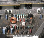
Frisbee78, soory I didn't respond sooner, you know how work goes. I've seen other's responses to your amp problem and they're right, and I don't want to sound redundant. However, I've looked at your pictures and will post one here. Check the components shown in the picture, they'll be shown in the white circles.
Please bear with me, as I'm new to this board. Hopefully, this will help you. I got the model number of your friend's receiver, and I'll try to locate a schematic. Take care and be good!

Please bear with me, as I'm new to this board. Hopefully, this will help you. I got the model number of your friend's receiver, and I'll try to locate a schematic. Take care and be good!
Attachments
Thanks everyone for your help.
I identified another dead resistor and replaced every transistor of the channel, just to be safe. All diodes checked out ok.
Tried the lamp trick when first turned on the amp and after some hesitation switching on, it went on security. Not very encouraging but after 10 mins of switching it on & off, it eventually went back to normal. I switched through all modes and everything was fine. I took the lamp off and tried again: all ok. But the next day, I connected some speakers on it and it blew sky high on power on. 🙁 No idea what the eck is wrong with that thing but after vaporising the most part of $30 in parts, it's going to scraps. I can probably buy an identical second hand amp for not much more money.
Thanks all for your help.
Seb
Hi all
sorry I missed all the fun but thanks for the light bulb trick. I'm going to wire up a short plugtop and socket extension with an in line bulb and hold on to it as part of my test kit!!!
regards
Andrew T.
sorry I missed all the fun but thanks for the light bulb trick. I'm going to wire up a short plugtop and socket extension with an in line bulb and hold on to it as part of my test kit!!!
regards
Andrew T.
I suspect that you might be having a problem with counterfeit devices (or you're bias is so far misadjusted that you're smoking it). Using the lamp trick, if the lamp only had a soft glow to it with in-circuit. then it promptly blows up with the lamp removed, then output devices are suspect (been there, done that, bought the T-shirt).😡I switched through all modes and everything was fine. I took the lamp off and tried again: all ok. But the next day, I connected some speakers on it and it blew sky high on power on. No idea what the eck is wrong with that thing but after vaporising the most part of $30 in parts, it's going to scraps.
Frisbee...
You need to change the four .22 resistors that got hot. Even though they seem to measure fine, I would be willing to bet that they are substantially out of tolerance...Personal experience has shown that when you lose outputs, the load balancing resistors almost always change resistance because they can't take the heat... If you don't change them, then you switch the power back on and the outputs get very hot in an instant and poof you cascade back into the drivers etc... Then magic smoke comes out again... :-(
Also, you mentioned that you checked the diodes. How? Did you actually lift one leg from the board or did you measure in circuit? If you did it in-circuit, you might have missed one... Often the only real way to check them is lifting a leg...
You might also measure across each of your caps in the circuit. Perhaps one is shorted and sending rail voltage into the circuit someplace where it's not supposed to be...
Here's what I'd do:
-Pull all of the transistors from the circuit.
-Lift one leg of all of the diodes and check them again.
-Measure across each of the electrolytics looking for a short (you can do this with your voltmeter) Swap the leads and the meter should jump full scale and slowly drop down as the cap charges. Reverse again and again is should peg then drop as it charges. IF the meter shows either a full short or open, then the cap is shot...
-Measure across each resistor looking for shorts even if they don't look burned. If you find a short, look at the associated components.
-Check to make sure that the amp's speaker terminals haven't cracked or somehow been damaged that would let the positive output connect to ground. This could cook output and drivers very quickly...
-Check each of your replacement transistors out of circuit to ensure that they are good before you solder them in.
-Solder all transistors back into the circuit.
-Connect one leg or your voltmeter to ground and then measure various points in the circuit comparing to the good channel. What you're looking for here are readings that are similar. They won't be exact but they should be pretty close. Go back and forth between channels. If you find an area of the circuit where one reading is very different to the other (think open or short) then you need to do more checking...
Also, I don't know the amp, but the only other thing that comes to mind is power supply. I once ran into something similar where the amp had separate bridge rectifiers for each channel. One of the rectifiers had partially failed and it was sending partially rectified voltage into the circuit. It cooked parts several times before I figured it out... (I didn't know about the lightbulb trick back then...)
Yea, it's frustrating... Look at it as a challenge and a learning experience... Don't let it beat you!!!
Good luck,
- Status
- Not open for further replies.
- Home
- Amplifiers
- Solid State
- Amp repair failure