That's the TransNova concept. Acoustat and Hafler used this idea.
The front section does not need to work on high voltage so you can use small and fast semiconductors. Its a nice concept.
But you need more power supplies.
Google it.
The front section does not need to work on high voltage so you can use small and fast semiconductors. Its a nice concept.
But you need more power supplies.
Google it.
Not separate, all the same ground.
The concept promotes mentioned small & fast front end semi's, on cost of impeccable power supplies (indicated with the battery symbol).
Either way, power supplies are always more or less in the signal path, so what's the advantage? Did the revenues of Acoustat and Hafler explode after putting their machines on the market?

Tubecad has an example of much the same thing using a diamond buffer wired like that so it could provide 6db of gain.
Electrically is the same. I saw it some years ago repairing an amp from a synagogal. I didn't know who had the idea, but very rare concept. I wonder the signal elevated trafo's capacitance to line, if it can cause more problems than those it is supposed to overcome.
The complexity and cost of multiple supplies is a big discouragement, and I suspect its really confusing to diagnose faults when the supplies are floating like this.
Why? The only change is that the output stage is inside-out compared to a "normal" amp, and noise is usually generated by the front-end anyway.Noise is another issue
Advantage is that it makes bridging the two halves of a stereo amp cheaper. Very common practice in the PA market. Peavey made a lot of money selling this pattern. Disadvantage it requires 2 rail windings in the transformer, 2 $2 bridge rectifiers and 4 rail filter caps. As 2 x 10000 uf filter caps are cheaper than one 22000 one, probably saved money right there. Kept design from requiring screw terminal rail caps which are extremely expensive these days. Another advantage wiring is 10 ga yellow ring connectors, instead of 6 ga wire and expensive 6 ga crimp terminals. Another advantage on 8 to 20 output transistor models, output transistor PCB traces can be thinner.
I just rebuilt two DC power supplies for organs, 15 v 30 A and 50 A. Those screw terminal caps are expensive, the 8 ga wiring is difficult to handle. those 1/4-28 screw terminal diodes are nearly extinct now, and were expensive in 1980 when these were built.
I just rebuilt two DC power supplies for organs, 15 v 30 A and 50 A. Those screw terminal caps are expensive, the 8 ga wiring is difficult to handle. those 1/4-28 screw terminal diodes are nearly extinct now, and were expensive in 1980 when these were built.
Last edited:
That.it requires 2 rail windings in the transformer, 2 $2 bridge rectifiers and 4 rail filter caps. As 2 x 10000 uf filter caps are cheaper than one 22000 one, probably saved money right there.
And the "disadvantage" is even smaller
1) when winding *large* power transformers, way too thick wire becomes unconteollable , do not bend well at corners, etc, so it´s *common** practice bifilar winding using two half section wires, then soldered in parallel.
Nothing stops sending them to separate terminals and voila! , now you have "free" dual windings.
2) some manufqcturers use two power transformers (and supplies) to keep amp height inside a 2U rack amp.
Again, using them as grounded output amps means no extra cost.
Bridging two amps just requires an inverter - which doesn't change cost between conventional and this scheme. Two half-sized supplies is usually more cost than one large supply unless you've crossed a threshold such as needing a soft-start circuit, or 3-phase line input or some such. And you still need the separate low voltage supply, ie three separate supplies to operate a bridged pair of amps with this scheme, v. one supply conventionally (assuming the low voltage is dropped using zeners/regulators from the main supply).
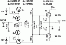
The output stage has voltage gain, since the output devices are operated in the common source mode.
QSC or Shure have used this system for many years, it helps when bridging power stages together.
This particular example also shows the output devices can probably be bolted onto the heat sink without insulating thermal pads.
This particular example also shows the output devices can probably be bolted onto the heat sink without insulating thermal pads.
You mean the CFP output devices in posting #5? Yes, that's an advantage. Also lateral MOSFETs have source as the substrate rather than drain so could be similarly shorted to heatsink. A bipolar EF style output-section would still need isolation.
VR1 and VR3 set the DC balance, VR2 and VR4 the bias of each stage. Surely they are interdependent, so an adjust of one of them implies the readjust of the others.
Hi all, i have small update. I built first part, with just a jfets and drivers. Works fine. I google translated the evolve amplifiers web page, as to familiarize myself with the design.
First section works fine, 100 ohm pot has very effect, but 500 ohm affect distortion a lot, its lowest at max settings, so i may insert some resistor there, rather than changing the pot.
Vr3 works perfectly to adjust dc balance, vr1 not so much.
I like it so far.
First section works fine, 100 ohm pot has very effect, but 500 ohm affect distortion a lot, its lowest at max settings, so i may insert some resistor there, rather than changing the pot.
Vr3 works perfectly to adjust dc balance, vr1 not so much.
I like it so far.
- Home
- Amplifiers
- Solid State
- Amp out grounded, power supply as output, why?