Total newbie, just finishing (well, almost) building the Amp Camp Amp. I turn it on, and the good news: the led lights come on. The bad news: it turns off right away. And then it turns on again, etc. This is on both sides, so the problem must be shared. Could it be the ground bus wire in the back? Any ideas? Thanks in advance
Please post well lit and focused pictures of your amp. Please include overall views of the whole amplifier that show all of the wiring and detailed views.
Is it the latest V1.8?
Is it the latest V1.8?
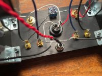
Here are some pics of the back panel. I was worried about the switch, but 1) it looks like I did manage to keep the middle white wire separate (though perhaps some solder connects it to the top) from the top position, and 2) when I tried it in different positions the response was the same. It is the latest v1.8. As you can probably guess by looking at these pictures, this was my first time soldering.


Please post well lit and focused pictures of your amp. Please include overall views of the whole amplifier that show all of the wiring and detailed views.
Also a clear view of the wiring of the DC input jack is needed. As originally requested, overall views of the whole amplifier please.
Pass DIY Addict
Joined 2000
Paid Member
It looks like you have some suspect solder joints. The solder blobs on that blue switch look enormous - have you inadvertently shorted the pins? Also, the positive speaker terminal on the right side of the image does not look like it has enough solder on it. Based on these two observations, I would recommend a careful inspection/clean up of your solder joints.
First timer here. Had a great time putting my ACA together. I connected the power supply, flipped the switch, and...nothing. No lights, no sound...zip. Here are some shots of my build. The switch works, the solders seem solid. Does anything jump out to anyone as an obvious mistake? Many thanks for any help!
Attachments

Pass DIY Addict
Joined 2000
Paid Member
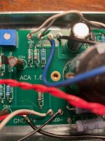
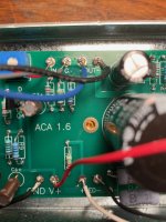
It looks like you have cold solder joints on the IN and G pads in your third and fourth images. The solder should flow smoothly and evenly across the entire pad leaving a bit of a peak where it hits the wire.
I would recommend taking your volt meter and probing around a little. Look for voltage at the PCB end of your red power supply wires. Make sure the polarity is correct. Since you are having problems, completely disconnect one PCB from the power supply - work on only one side at a time until you have solved problems. If you have wired something incorrectly and then powered up both boards, you have potentially caused problems on BOTH boards. No need killing more than you need to with a silly mistake. I know because I've been there and done that.
A few steps:
Check polarity of your power supply
Dismount your PCB, check/reflow all solder joints, make sure the solder has melted to a warm solder pad
Take a fine-tipped flat blade screwdriver and physically scratch the PCB between ALL adjacent solder pads to remove potentially invisible solder bridges between pads. Use a bright light and a magnifier glass. Don't trust or guess, scratch between every pad.
Make sure you don't have long wires going through the PCB and grounding on the heat sink behind the board. Snip closely to the PCB after soldering.
Double check mosfet mounting. Using your DMM and look for any connectivity between the middle pin and the sink. It should measure open loop, if not, you have an electrical short. Throw away the pad you used and use a new pad to remount the mosfet.
The leads on your power indicator LEDs are bare as they travel through your front plate. Remove and add new heat shrink that covers the entirety of the leads after they've been soldered.
Be patient. Be methodical. You'll find it and it will make beautiful music!
Looking at the back plate, it looks like you need to do some re-work. Look at the V1.8 guide very carefully on that wiring.First timer here. Had a great time putting my ACA together. I connected the power supply, flipped the switch, and...nothing. No lights, no sound...zip. Here are some shots of my build. The switch works, the solders seem solid. Does anything jump out to anyone as an obvious mistake? Many thanks for any help!
- All RCA/Switch/XLR wiring
- Resistor to speaker terminal, not RCA
- Get some more solder on those connections on the back plate.
I can't quite see on the LED's, but is there a chance the LED exposed lead could touch the chassis? If so, slide that heatshrink down to the LED if possible.
Oh. Well that would make a difference, wouldn't it? 😉
Thanks to the three of you. I shall look at right diagram first, then go back over my solders. I'm a baker by trade, which is easier than this.
Thanks to the three of you. I shall look at right diagram first, then go back over my solders. I'm a baker by trade, which is easier than this.
Well, I updated the back panel wiring, and I redid every solder on both boards. Nothing. Then just to see I switched the wires on the LEDs and tried them. They were backwards the whole time.
This amp sounds amazing. Thank you again gentlemen. I learned a lot today, both about electronics and being an idiot.
J
This amp sounds amazing. Thank you again gentlemen. I learned a lot today, both about electronics and being an idiot.
J
Having long bare wires then soldered at the tip is bad practice.
The insulation should be pretty much up to the point where it is soldered.
Lack of solder on some joints.
There are loads of soldering tutorials on youtube.
The insulation should be pretty much up to the point where it is soldered.
Lack of solder on some joints.
There are loads of soldering tutorials on youtube.
Appears that a good course in proper soldering and wiring should be the first section
in all of the build guides here.
in all of the build guides here.
The switch has some big lumps of solder on it. Even looks like a short on bottom.
It should be enough to solder the wire and hole be covered.
It should be enough to solder the wire and hole be covered.
Pass DIY Addict
Joined 2000
Paid Member
Glad to hear you got it working! It’s usually something simple, but not always easy to find!This amp sounds amazing. Thank you again gentlemen.
- Home
- Amplifiers
- Pass Labs
- Amp Camp Amp startup problem