I have another Auna ALP404CH amplifier. Interesting amps, the other cheap amplifiers usually blow only outputs and sometimes PS FETs and thats it but these have some weird issues, every one of them
One of my first attempts to fix an amplifier is here, also Auna ALP404CH: http://www.diyaudio.com/forums/car-...-exessive-current-when-speaker-connected.html
When powering up amp is in protection, then it tries to switch on but goes back to protection, after few seconds tries to power up again, draws current, something crackles and one of the PS FETs on one side fails, I have current limiting headlamp inline with B+.
Gate resistors and drivers are already replaced. I also replaced 494.
It does this with and without rectifiers installed.
When I do not install PS FETs on the problematic side of the amp and disable protection via lifting few jumpers near 494 all channels produce clean audio.
If protection is disabled and all PS FETs installed amp still draws too much current and blows one of the FETs.
If I remove the blown FET but leave others in, amp draws too much current but does not blow any more FETs, if I leave only one FET in the problematic side then amp does not draw too much current.
With 3 FETs installed and transformer from the problematic side removed amp still draws too much current. When the other transformer is removed then amp does not draw current but does not come out of protection either.
Remove the FETs. For every FET, install a 1k resistor from gate to source. Does the drive signal remain clean and square?
What if you connect the resistor from the gate to the drain?
Do this for one FET at a time.
What if you connect the resistor from the gate to the drain?
Do this for one FET at a time.
That would seem to eliminate the drive circuit as the fault if you checked the signal on the gate pad for the FETs.
For the FET that repeatedly blows, double-check the drive signal while pushing on/flexing the circuit board. Does the waveform ever change from a perfect drive signal?
I pulled all Fets, tried the same thing with other side of the board, also all nice squares.
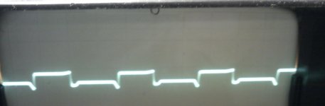
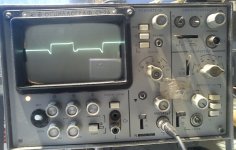
Then i put in new FETs in the problematic side. Two of them blew. Left good ones in, installed 1k resistors from gate to drain in place of blown FETs on one I get clean square, on the not so clean, see first attached photo. Square is clean on the 494 side of the gate resistor.
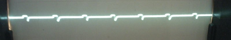
Also there is a waveform on 22 ohm resistors coming from 494 and going to transformers, I have never checked if there is just +12V or some waveform, anyway, what I saw on those resistors is on second photo.
Then i put in new FETs in the problematic side. Two of them blew. Left good ones in, installed 1k resistors from gate to drain in place of blown FETs on one I get clean square, on the not so clean, see first attached photo. Square is clean on the 494 side of the gate resistor.
Also there is a waveform on 22 ohm resistors coming from 494 and going to transformers, I have never checked if there is just +12V or some waveform, anyway, what I saw on those resistors is on second photo.
Attachments
When you post screen caps from your scope, you need to include the timebase and vertical amp settings. When displaying this type of waveform (drive signal for an FET), you should set the trace on the reference line of the display and set the coupling to DC. This is covered on page 67 of the car audio site.
Some new screens of waveforms I found from the amp.
Timebase for all photos: 5us, vertical: 2V
First photo is gate signal on a FET.
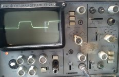
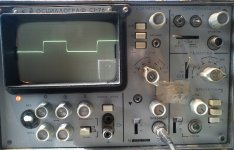
Second and third photo are gate signal on gate pad with 1k resistor connected from gate to drain, both are driven by the same driver transistor.
Timebase for all photos: 5us, vertical: 2V
First photo is gate signal on a FET.
Second and third photo are gate signal on gate pad with 1k resistor connected from gate to drain, both are driven by the same driver transistor.
Attachments
If the scope is set to 2v/div, it appears that the NPN driver transistors don't have sufficient DC voltage on their collectors.
Are you sure that those are the right transistors?
Unless this amp uses a drive circuit that's very different from most amps, that transistor should be a PNP transistor.
Does this amp use an emitter follower pair (NPN and PNP transistors) for the drivers?
Unless this amp uses a drive circuit that's very different from most amps, that transistor should be a PNP transistor.
Does this amp use an emitter follower pair (NPN and PNP transistors) for the drivers?
It is PNP transistor.2SA1015 is printed on the board on all 4 locations for drivers. Two have their bases connected to pin 9 of 494, two of them to pin 10 of 494.
All collectors tied to ground, emitters connect to gates of two IRFZ44N through a 100 ohm resistor.
All collectors tied to ground, emitters connect to gates of two IRFZ44N through a 100 ohm resistor.
I misread the part number. Does the amp use any NPN drivers or does it have a diode connected across the base and emitter of the PNP driver?
If it uses a diode, what is the DC voltage on pins 11 and 12 of the 494?
If it uses a diode, what is the DC voltage on pins 11 and 12 of the 494?
Why is your power supply producing only 10.2v DC?
What is the amplitude of the square wave on pins 9 and 10?
How does that compare to the voltage on the gates of the FETs?
What is the amplitude of the square wave on pins 9 and 10?
How does that compare to the voltage on the gates of the FETs?
- Status
- Not open for further replies.
- Home
- General Interest
- Car Audio
- Amp blowing PS FETs