Imgur: The most awesome images on the Internet
As i'm designing this for guitar/bass use, i've omitted the input transformer.
The first cathode bypass cap is .005 uF and i'm intending to make it switchable.
The schematic shows a Hi-Z to low-Z OPT, but as it's a parallel cathode follower, dc coupled to the previous stage,the output impedance should be low enough (somewhere around 310 ohms if I remember correctly)so i'm just using a 1:1 transformer (600:600 Palmer transformer). I've also a added a 2k grid stopper on V1b.
Valvewizard has an interesting text on dc coupled cathode followers: " If a down-going signal appears at the gain stage's anode the grid voltage of the follower is pushed down back into the area of "normal operation", and grid current stops flowing more or less immediately, for the duration of that cycle. But when the incoming signal is positive going the grid is pushed more positive, which induces even more grid current to flow into the cathode follower as it tries to maintain bias, which in turn 'drags down' the anode voltage of the gain stage which is trying to move positive! In other words, the up-going cycles are very heavily compressed, but the down going ones are not, which generates a lot of second harmonic distortion. This is only made possible by the DC coupling, and is why this circuit is so often used in high gain amps- it can warm up a signal that already contains too many high-order harmonics, and return a rather fuzzy sound to a rich, creamy distortion tone."
-Which is the reason of the switching cathode bypass caps between V1a and V1b and the selectable .005 cathode bypass cap in V1a.
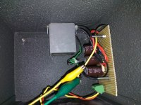
The meter originally in the chassis is broken, so i'm using it as a viewing glass for the tubes.
As i'm designing this for guitar/bass use, i've omitted the input transformer.
The first cathode bypass cap is .005 uF and i'm intending to make it switchable.
The schematic shows a Hi-Z to low-Z OPT, but as it's a parallel cathode follower, dc coupled to the previous stage,the output impedance should be low enough (somewhere around 310 ohms if I remember correctly)so i'm just using a 1:1 transformer (600:600 Palmer transformer). I've also a added a 2k grid stopper on V1b.
Valvewizard has an interesting text on dc coupled cathode followers: " If a down-going signal appears at the gain stage's anode the grid voltage of the follower is pushed down back into the area of "normal operation", and grid current stops flowing more or less immediately, for the duration of that cycle. But when the incoming signal is positive going the grid is pushed more positive, which induces even more grid current to flow into the cathode follower as it tries to maintain bias, which in turn 'drags down' the anode voltage of the gain stage which is trying to move positive! In other words, the up-going cycles are very heavily compressed, but the down going ones are not, which generates a lot of second harmonic distortion. This is only made possible by the DC coupling, and is why this circuit is so often used in high gain amps- it can warm up a signal that already contains too many high-order harmonics, and return a rather fuzzy sound to a rich, creamy distortion tone."
-Which is the reason of the switching cathode bypass caps between V1a and V1b and the selectable .005 cathode bypass cap in V1a.
The meter originally in the chassis is broken, so i'm using it as a viewing glass for the tubes.
Last edited:
She sounds good!
Here's a recording I did, just the guitar to the altec, altec line out to Apogee Duet line in (on a crappy bass, hence the high pitched noise): Altec 1566 Bass Recording by Mk5 Studios | Free Listening on SoundCloud
First is low gain, second is, obviously, high gain. There's no (at least to me) audible hum. Overall I'm more than happy with the result. It even already had to save the day because there weren't enough DI boxes for a show I was doing PA for!
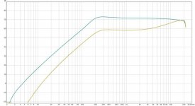
The graphs you see are with and without high boost enabled (inductor to ground after first preamp stage that is switchable)
After all, I didn't make the cathode bypass cap switchable, as the effect was not enough as I'd hoped for.
I really like the sound of this thing in front of a small tube amp, both at full gain. Sounds a lot like some marshalls to me!
Here's a recording I did, just the guitar to the altec, altec line out to Apogee Duet line in (on a crappy bass, hence the high pitched noise): Altec 1566 Bass Recording by Mk5 Studios | Free Listening on SoundCloud
First is low gain, second is, obviously, high gain. There's no (at least to me) audible hum. Overall I'm more than happy with the result. It even already had to save the day because there weren't enough DI boxes for a show I was doing PA for!
The graphs you see are with and without high boost enabled (inductor to ground after first preamp stage that is switchable)
After all, I didn't make the cathode bypass cap switchable, as the effect was not enough as I'd hoped for.
I really like the sound of this thing in front of a small tube amp, both at full gain. Sounds a lot like some marshalls to me!
Attachments

Last edited:
- Status
- Not open for further replies.