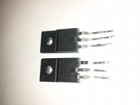
hi everyone I just signed up and thought ide start sharing my repair work so that hopefully others may get some useful information from it, I'm only learning my self and I feel ide give something back for all I've learnt from others on here, so to start with I have a Alpine mrv-f545 with blown fuses and oc on the display before it blows fuses,, I've already played a bit with this amp so I'll try to get pics and my progress up next, thanks
Same type number, different production codes... so yes the same.
Failure or overheating of output devices is usually a sign of a problem elsewhere such as drive issue.
Failure or overheating of output devices is usually a sign of a problem elsewhere such as drive issue.
ok well this is what I thought, production code, but I've got a data sheet on the fkv-550 t and fkv-550 n and the difference is something in the gate voltage, I'm wondering if the t and the n are actually different part numbers and therefore I'm getting some overlap somehow in the power supply, its strange because the t is rated lower gate voltage. and the reason I say all of this is yes the amp has dual power supplys , it has 4 fkv,s per supply, but I still have 4 good fkv550n,s and if I power the amp up with just those 4 it powers up one power supply fine, +37 -37v but then I can take those 4 out put 4 of the fkv550t,s in and as soon as they start switching they start burning up and the voltage starts drooping, the gate voltage is fine at 5.20v at 26hz I think, and I know the fkv550t,s are good because I just put them back into the kenwood amp they came from and it works, next in going to measure the gate voltage in the kenwood, maybe they are pro codes but they came from the factory with slightly different carachteristics so they had to make a different data sheet? I'm not sure on this one all I know is I have a fkv550t and fkv550n datasheet and they different, and I never would have thought the t or n down where its printed would be anything to do with the data, ill post the outputs too because there is numbers on the bottom of them and the funny bit is the ones with the other numbers run the lower power ch 1,2 on the amp, which has 4 output transistors compared to the 3,4 channel which has 8
Have to admit that that does point to a difference... if if it works OK with one variant and not the other.
You need to look at the actual gate drive voltage available from whatever drives these FET's and compare with the data sheet. Look to see at what Vgs the device is guaranteed to be fully conducting and see how that compares to the data sheets. If the gate drive is insufficient to fully turn on the FET's then will be operating partly in a linear mode and that would explain the heat generation.
You need to look at the actual gate drive voltage available from whatever drives these FET's and compare with the data sheet. Look to see at what Vgs the device is guaranteed to be fully conducting and see how that compares to the data sheets. If the gate drive is insufficient to fully turn on the FET's then will be operating partly in a linear mode and that would explain the heat generation.
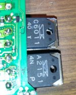
here are the outputs, notice the 4n p and 40 y on the bottom, there is 2 a,s and 2 c,s with one number for the small channels and 4 and 4 of the other for the other larger 2 channels, these ones might be nothing but I just want make sure before I replace the one blown one
Attachments
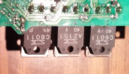
They might refer to gain groups (hfe range) but whether its of importance I wouldn't like to say. For devices that are in parallel matching helps ensure current sharing etween devices.
I'm thinking probably the same with the outputs, even though both are full range outputs, one is bridgable and more than likely is going to be used as a sub channel, I'm still learning some basics so excuse me if I ask or say something noobish,
That shows the T version will operate in saturated mode with a much lower gate drive voltage than the N version. Looks as though that is the reason for the overheating. I'm guessing the drive voltage is from 5 volt logic for that to happen.
I'm thinking probably the same with the outputs, even though both are full range outputs, one is bridgable and more than likely is going to be used as a sub channel, I'm still learning some basics so excuse me if I ask or say something noobish,
Its no problem 🙂
(and I'm working without circuit details so likely to say something inapplicable 😀)
Matching of transistors comes into its own when they are operated in parallel. Fo all the devices to share equally so that none hog the current and overheat and fail its important to match them, more so between the same device types rather than NPN vs PNP
and this is the last page, anyways I think I still have other problems in not too sure, especially being two power supplys how they work together or mainly how they tell the amp everything is ok and to output sound, I could post a circuit pic its pretty straight forward, I just think I've gotta get the right fkv,s or similar and a whole 8 to match before I go further, its good learning though on the way, I had two small 16volt e capacitors blow too, and I think its because I had the extra board with the extra 2 channels unplugged when I powered it up, ide have to explain in more detail what I did but I'm probably more realising now that u can't just power up things with certain parts unplugged or missing without power surges or things happening that shouldn't.
Attachments
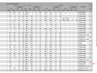
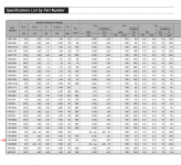
Hmmm... little difference there other than the turn on voltage we mentioned before. The T version has slightly higher transconductance (the FET equivalence... well sort of... of gain) and slightly lower guaranteed on resistance, 10 to 13mΩ vs 12 to 15mΩ.
It seems like its going to be the turn on volts thats the critical parameter here.
It seems like its going to be the turn on volts thats the critical parameter here.
I'm not too sure exactly how to read it with my dmm but by memory it read 5.20volts dc at the gates, I flicked it to hz reading and it said 26hz I think, so yeah my quess was the t,s were overlapping or whatever the term is, makes sense cause the voltage dropped from 12 to like 7 real quick as the power supply started, ill do a test on the kenwood amp the t,s came out of and see what thats saying I might be able to change the gate resistors maybe, I noticed the kenwood is also running the same TL-594 pwm chip
A DVM isn't really suited to measuring things like this, you need a scope. Switching supplies run at many kHz (anywhere from 30kHz to several hundred kHz). Overlap or cross conduction occurs when there is insufficient "dead time" (a period when neither FET conducts). Again, a scope is needed to see whats going on.
i know bottom line is I need the same parts with same specs, it just threw me a little until I realised the t,s were different, I was obviously checking the transformer windings the bridges and caps, 6 times over before I put the original 4 back in and it worked,, and by worked I mean just one side of the amp, one power supply.
I was thinking of trying some irf-1010ez,s I think they cheap and they are supposed to be a replacement I think, ill do some more research, maybe I can get 4 550n,s somewhere, I also have another v12 alpine amp here somewhere I know has the same outputs in it maybe its got the 550n,s, I'm still a little worryed why two little 16volt caps blew.
Certainly for the FET's you do. There may well be suitable substitutes, I'm just not familiar with any of the devices commonly used in car audio gear and so can't just rattle any off 😀 Others reading this may well know of suitable substitutes.
i apreciate your input too mate, ill get back to it and play a little more, its reassuring at the least that someone shares the same thoughts. will update here as I go, thankyou
- Status
- Not open for further replies.
- Home
- Amplifiers
- Class D
- Alpine mrv-f545 repair