The transistors that I'm seeing for the 1W mark are all high voltage, low current. Not what I'd expect for a regulator.
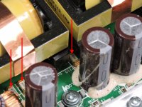
Can you measure the DC voltage across the collectors of those two transistors?
Can you measure the DC voltage across the collectors of those two transistors?
Yes. You can measure from collector to ground of across the collector pads for the two transistors.
From ground to collector of q304 : -54.3
Measured directly across collectors I get 66.8
Measured directly across collectors I get 66.8
Last edited:

Replaced the resistor and Q304
Something still isn't right ..
Both regulators were defective and they are out of the amp right now..
On the input legs for the regulators what voltages should i see?
I'm getting pulsing voltages from 0.00 to 2.00
Something still isn't right ..
Both regulators were defective and they are out of the amp right now..
On the input legs for the regulators what voltages should i see?
I'm getting pulsing voltages from 0.00 to 2.00
Q311 is the one you should have replaced with the 06. Is that what you did?
Are these the regulators that you're referring to or IC104/5?
Are these the regulators that you're referring to or IC104/5?
Sorry my mistake I replaced Q311 with the A06
Yes IC104 and IC105..
I don't think the power supply is working correctly
On some of the power supply fets i get 13 volts on the middle leg on the others I get 0.04 on the middle leg
Yes IC104 and IC105..
I don't think the power supply is working correctly
On some of the power supply fets i get 13 volts on the middle leg on the others I get 0.04 on the middle leg
You may have blown surface mount fuses. They're under the transformer. They're no fun to change. You can jump one of the open fuses (there are multiple in parallel in two or four groups) with a wire for testing (through a limiter).
As soon as you get it to power up fully, quickly re-check the voltage on Q304/11. If the voltage is greater than about 70v (referenced to ground), change the 06 to an MMBTA42.
As soon as you get it to power up fully, quickly re-check the voltage on Q304/11. If the voltage is greater than about 70v (referenced to ground), change the 06 to an MMBTA42.
Attachments
Checked all of them and they test good ..
I redid some solder connections and on half of the fets I get 13 volts on the middle leg and the other half I get 7 volts on the middle leg .
Is this normal or where should I start to check ?
I redid some solder connections and on half of the fets I get 13 volts on the middle leg and the other half I get 7 volts on the middle leg .
Is this normal or where should I start to check ?
That probably means that the power supplies are being driven in h-bridge configuration. This is going to make it more difficult to troubleshoot without a diagram.
After reflowong the solder on the legs of all the power supply fets this is what I get now ..
On half of them I get 0.04 ohms to ground
On the other half I get 15.12K to ground ..
So I'm gonna need a schematic to figure this out correct?
On half of them I get 0.04 ohms to ground
On the other half I get 15.12K to ground ..
So I'm gonna need a schematic to figure this out correct?
I can't say whether you'd need a schematic to repair it but I'd probably need one to help if the power supply has no bad components but won't start.
- Home
- General Interest
- Car Audio
- Alpine MRP-M2000