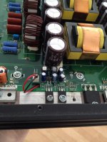
Got another one of these amps..
Amp had alot of damage to it..
So far ive replaced
All 8 of the power supply fets --IRF3205
All 8 of the outputs-- IRF3415
The regulators Q9301,Q4901 with C2690A-Y
Q9302 with A1220A-Y
ZD4901 12 volt zener
Driver IC's IR2010S
IC9702: 14069U
IC9703: 14081
IC9704: 14069U
D9804: MURS120
Anything else i should check before applying power to this amp ??
The amp likes to blow outputs and ZD4901 and Q4901
Ok replaced 3 6.8 ohm resistors as well...
Powerd the amp up no output..
I do not get rail to rail oscillation any ideas on where to check?
Powerd the amp up no output..
I do not get rail to rail oscillation any ideas on where to check?
Ok something is not right here..
According to the service manual on Q4901 i should have -34 volts on the collector ..
Im getting -47 volts and the regulaor keeps blowing..
Any ideas?
According to the service manual on Q4901 i should have -34 volts on the collector ..
Im getting -47 volts and the regulaor keeps blowing..
Any ideas?
What am i missing here?
Everytime i power this amp up it blows ZD4901,Q4901 and all 3 of the IC's
IC9702,IC9703,IC9704
Anyone have any ideas?
Everytime i power this amp up it blows ZD4901,Q4901 and all 3 of the IC's
IC9702,IC9703,IC9704
Anyone have any ideas?
You should apply heatsink compound between the regulators and the heatsink.
Are the transistors you used for the regulators fully encapsulated or do they have exposed metal backs?
Are the transistors you used for the regulators fully encapsulated or do they have exposed metal backs?
Remove the blown ICs and replace the regulator transistor again. Does that change anything?
If it doesn't fail immediately, measure the output voltage of the regulator with the black probe on the negative rail and the red probe on the emitter of the regulator transistor.
If it doesn't fail immediately, measure the output voltage of the regulator with the black probe on the negative rail and the red probe on the emitter of the regulator transistor.
With black probe on negative rail heres what i get on the regulator..
Emitter: 7.41
Collector 47.0
Base: 45.6
I know these voltages are no where near correct
Any ideas on where to start?
Emitter: 7.41
Collector 47.0
Base: 45.6
I know these voltages are no where near correct
Any ideas on where to start?
If i use the amps ground terminal i get the correct voltages..
If i use negative rail i get the same redings as before after replacing the diode and making sure i have soild connections
If i use negative rail i get the same redings as before after replacing the diode and making sure i have soild connections
If I use amps ground terminal I get
-34 volts
0.00 volts
-34 volts
If I use negative rail I get the readings listed in previous post
I don't get voltage on pin 7 of the driver ic's any ideas where to start looking?
-34 volts
0.00 volts
-34 volts
If I use negative rail I get the readings listed in previous post
I don't get voltage on pin 7 of the driver ic's any ideas where to start looking?
I can't think straight tonight do you happen to have a photo of where I put the meter leads to test resistance
Perry,
If I stick 1 probe on main ground terminal where do I stick the other probe to get the resistance ?
If I stick 1 probe on main ground terminal where do I stick the other probe to get the resistance ?
With no power applied, you can use the outer terminals of the rectifiers. This only works with no power applied.
Do this with no RCAs plugged in.
Do this with no RCAs plugged in.
- Status
- Not open for further replies.
- Home
- General Interest
- Car Audio
- Alpine MRP-M1000