Hello,
I have had this trusty amp in my truck for the last 10 years running in 4 channel mode for my front and rear speakers, about a month ago it started acting up and would at times not turn on then while driving down the road it would randomly just come on, I found out that if I gave it a tap it would turn on/off.
I finally got around to tearing it out of the truck today and got it on the bench, I found the culprit was two large ~1w resistors just to the right of the four large power supply caps, unfortunately they're not labeled, but they had came loose from the board I assume from vibration. I took the board out and reflowed the solder around them and put it back together. The amp fired right up and turned on/off reliably and didn't shut off with any sort of tapping or shock to the board. Great I'm thinking its fixed right.
So I hooked it up on the bench and immediately noticed that the idle current was very high ~6-7amps and the amp was running so hot that I couldn't even touch it. Even though it seems to play fine in all channels with all combinations of inputs and crossover settings. Anyone have any clues on what to check now? or any schematic, couldn't seem to locate anything via searching.
Thanks for any help
Mike
The bias current may be set too high. Measure and post the DC voltage across the outer legs of each of the large white emitter resistors. Do this with no speakers or signal cables connected to the amp.
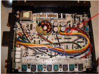
Thanks for your help Perry. I just measured the resistors, which I'm assuming are the 4 next to the output transistors the longer flat white ones that have 3 legs, they are labeled Hanami MPR 3W 0.1ohm J x2 the voltage values from left to right in the picture above are below measure with a Fluke 87 meter referenced to the B- terminal on the amp. Also I noticed when the amp is cold the idle current is ~13amps then settles to ~7amps when things get nice and toasty, this thing is very hot. I also checked the rail voltages via the center legs on the output transistors (or at least I think that's what it is, correct me if I'm wrong) and it seemed reasonable at roughly plus and minus 21v.
-.030
.059
-.029
.047
-.045
.057
-.010
.047
Mike
-.030
.059
-.029
.047
-.045
.057
-.010
.047
Mike
Last edited:
Ahhh..OK apparently I can't understand the term across...
Here are the 4 voltage values left to right in the pic above of the same resistors measured on the outer two legs of the three. Negative probe was to the left in all measurements.
.120
.104
.128
.079
Mike
Here are the 4 voltage values left to right in the pic above of the same resistors measured on the outer two legs of the three. Negative probe was to the left in all measurements.
.120
.104
.128
.079
Mike
That seems to be a bit high. I'm assuming that that's approximately 0.1v and not 0.1mv.
Are there any potentiometers near the emitter resistors?
The resistors that melted out of the board may be for the ±15v regulator. Are any of the 8/9 pin op-amps running hot?
Are there any potentiometers near the emitter resistors?
The resistors that melted out of the board may be for the ±15v regulator. Are any of the 8/9 pin op-amps running hot?
Yes, that is ~.1v and no there are no pots anywhere on the board excepts for the user controls at the end plate. I'll go check the op amps now, I'm assuming you mean the long skinny black components with 8/9 pins, sorry not an electronics expert by any means... I do appreciate your help greatly though.
Mike
Mike
Yep, the four larger ones that are close to the resistors I measured earlier are smokin hot, they all are the same part number and have a small metal heatsink built in to the tops of them that is painful to touch. All the remaining smaller black IC's are not warm.
Mike
Mike
What is the DC voltage measured between the center legs of the two output transistors for any of the channels?
What is the DC voltage measured between the center legs of the two output transistors for any of the channels?
The're all right around 41.4v
Are all of the output and biasing transistors clamped to the riser plate?
If by "riser plate" you mean the heatsink then yes there are 8 output transistors and the 4 biasing transistors between them, they all have one screw each and are bolted to the heatsink with the thermal compound and one of those thin clear insulators each. I've never turned it on without them bolted up, the aluminum chassis/heatsink gets very hot in a hurry.
You can confirm that there is no oscillation on the speaker output terminals but I don't think that there's anything else you can check at this point. Have you replace any of the output or biasing transistors?
No, I haven't replaced anything in the amp, it all looks original and unaltered. Are you thinking one of the output or biasing transistors could be bad? I'll check the speaker terminals with the scope.
It's likely to be a problem common to all channels like a power supply problem but, from the information you provided, I can't see anything that would cause a the high bias.
OK, I might be getting somewhere, was able to "fix" the amp by testing it with the o-scope, this is weird.
Scoped the 4 channels of speaker outputs from each speaker's - to +, they all seemed similar about 500mV peak to peak at ~140kHz
I then decided to check from the B- to the speaker terminals and as soon as I touched the scope probe to any of the speaker terminals + or - the idle current immediatly went to 1.0amps and everything cools off. Also does the same thing with the scope lead referenced to B+.
Next I unhooked the scope lead from the scope and I get the same behavior as above, this was with the scope lead in the 1X position, however in the 10X the idle current went back up to 7A.
I then tried a few resistors in place of the scope lead from 1meg to 4.7K with no effect on the idle current so doesn't seem to be a resistance thing. Not sure what's in a scope lead, capacitance maybe?
I guess I could sacrifice a scope lead to fix the amp...lol. Any ideas, weird one.
Mike
Last edited:
With no RCAs plugged in, what's the resistance from the RCA shield to the non-bridging speaker terminals?
Does it oscillate/overheat with no RCAs plugged in?
Does it oscillate/overheat with no RCAs plugged in?
A bit more info, checked the scope leads a bit closer and they have a capacitance rating of 18.5pF in the 10X position and 115pF in the 1X position, I had a ceramic 330pF laying around, tried in inbetween the B- and a speaker terminal and Bingo idle current goes to 1A. Must have a bad cap somewhere?
@Perry - Will go check right now on the resistance, and yes it overheats with no RCA's plugged in.
@Perry - Will go check right now on the resistance, and yes it overheats with no RCA's plugged in.
- Status
- Not open for further replies.
- Home
- General Interest
- Car Audio
- Alpine 3527S Repair