As a noob, I have been looking into cathode bias options and what initially started as just a few to choose from quickly multiplied into many.
So far, I have changed the Rogers Cadet output cathode biasing from single R (130 ohm bypassed with 40uF) shared between both output tubes to individual R (130ohm bypassed with 47uF cerafine). This made a noticable difference.
I rebuilt Cadet's power stage into Baby Huey stage and left this cathode bypassing in place - excellent sound from this new circuit - compared to the Cadet, it's more accurate, not as wooly as the Cadet.
I changed the biasing to battery (9v alkaline - I know it should be NiMh or NiCd) but didn't notice any diff in sound.
I'm wondering about other biasing schemes - I've seen mention of
CCS,
LEDs,
SY's Red Light District bank of LEDs
Low R from cathode to ground supplemented by additional current
80% bypassing where a low R & larger R are used with the Large R bypassed with cap
Are there others I should look at/try?
John
Oh forgot to mention - the low R cathode bias won the European Triode Festival Listening test beating Battery Bias, LED bias, etc.
http://db.audioasylum.com/cgi/m.mpl?forum=tubediy&n=83403&highlight=Huber&r=&session=
and here:http://www.tnt-audio.com/shows/etf04_e.html
Is this worth a try next - has anybody got first hand experience?
John
http://db.audioasylum.com/cgi/m.mpl?forum=tubediy&n=83403&highlight=Huber&r=&session=
and here:http://www.tnt-audio.com/shows/etf04_e.html
Is this worth a try next - has anybody got first hand experience?
John
That would have a turnover frequency of 26Hz - much too high, especially for an output stage. 470uF would be more like it. Also, if two tubes needed 130 ohms between them, then separate resistors would need to be 260 ohms each.130ohm bypassed with 47uF
I think the reason there are so many types of bias circuit around is because no one is best, they all have their strong and weak points. For me, it's fixed bias for the OP stage and cathode bias everywhere else - but that's just me 🙂
jkeny said:Oh forgot to mention - the low R cathode bias won the European Triode Festival Listening test beating Battery Bias, LED bias, etc.
An interesting result. I'll throw out a conjecture, it's been a consistent experience on the bench that the higher distortion components respond much more strongly to local degeneration than the predominant 2nd. A little impedance in the cathode circuit can knock 15 dB off, for example, the 4th or 5th with little to no visible impact on the 2nd. The ETF result correlates with my experience using bad - as in relatively high impedance - LEDs for cathode biasing, usually greens. Bypassing a green with a large cap often results in an increase in higher harmonic distortion components.
In your case though, which is an output, I agree 100% with everything Ray wrote.
I'll caveat Ray's comment with the sad trade-off: when we make that cathode cap bigger to reduce LF phase shift, we degrade recovery time after overload.
SY said:I'll caveat Ray's comment with the sad trade-off: when we make that cathode cap bigger to reduce LF phase shift, we degrade recovery time after overload.
could this effect be reduced by using lower-ESR caps such as metalized polyester?
No, it has nothing to do with the ESR, it is completely determined by the cap value. The recovery time is set by the time constant between the bypass cap and the parallel equivalent of the cathode resistor and the cathode impedance. At cutoff, the latter is quite high, so the cap can only discharge through the cathode resistor. Correct bias isn't restored for several time constants. So, you're stuck: if you increase the cap size for bass, you increase the recovery time.
Yes Ray,
Im sorry my figures were wrong in the posting - original shared R was 130ohm which I changed to individual 270ohm & indeed it was bypassed with 470uF starget cap.
I understand that there is no best bias scheme but there are theories behind each scheme:
For instance SY's LED matrix is premised on the idea that fast recovery time is at the heart of an excellent amp.
And rdf's comment on low R bias:
Does anybody know the theories behind the other bias schemes?
John
Im sorry my figures were wrong in the posting - original shared R was 130ohm which I changed to individual 270ohm & indeed it was bypassed with 470uF starget cap.
I understand that there is no best bias scheme but there are theories behind each scheme:
For instance SY's LED matrix is premised on the idea that fast recovery time is at the heart of an excellent amp.
And rdf's comment on low R bias:
I'll throw out a conjecture, it's been a consistent experience on the bench that the higher distortion components respond much more strongly to local degeneration than the predominant 2nd. A little impedance in the cathode circuit can knock 15 dB off, for example, the 4th or 5th with little to no visible impact on the 2nd.
Does anybody know the theories behind the other bias schemes?
John
Are there others I should look at/try?
http://home.att.net/~chimeraone/axiom300bschematic.html
http://home.att.net/~chimeraone/axiom300btestdata.html
jkeny said:CCS,
LEDs,
SY's Red Light District bank of LEDs
Low R from cathode to ground supplemented by additional current
80% bypassing where a low R & larger R are used with the Large R bypassed with cap
jkeny said:understand that there is no best bias scheme but there are theories behind each scheme:
For instance SY's LED matrix is premised on the idea that fast recovery time is at the heart of an excellent amp.
And rdf's comment on low R bias:
I don't have much more experience here than you do John, but I'll hazard a guess.
The CCS is essentially the opposite of an LED - very high vs. very low dynamic impedance. The CCS can be used to set the current operating point, as was done in a recent thread on 12B4 based preamps. It substitutes for a cathode resistor but with a more stable operating point. It would be bypassed and so would have the same considerations regarding blocking, capacitor selection for sound characteristics, etc.. - Not talking here about application beneath a long tailed pair.
The low R with extra current feed is an interesting one. I would guess that the downside would be it's sensitivity to the supply quality (or maybe upside, if you can work it out so that it cancels noise on the plate). A harder downside to get around, is that for an output stage, you could be burning off a lot of power in a low value cathode R. I would think it could be readily configured to avoid blocking problems by feeding it with a good voltage source, but again, that source is square in your audio path. It doesn't require a negative supply, but would it really be easier in most cases than fixed bias?
The 80% solution (could be any percentage) allows some degeneration at the cathode. rdf's comments apply here, so you might get a better distortion profile.
I'd be interested in other's comments/experiences.
Sheldon
I have used LED bias with supplementary current in my preamp stage. The supplementary current is supplied by a LM7805 over a simple resistor/LED voltage divider for quasi CCS. This brought considerably more clarity and impact over the LED without the supplementary current.
I also substituted the LED with a resistor and this sounded very good to, I went back to the LED.
The LM7805 produces a noise free current supplement which is very easy to implement. No hum from this preamp at at, at all.
Benefits clarity and punch.
Shoog
I also substituted the LED with a resistor and this sounded very good to, I went back to the LED.
The LM7805 produces a noise free current supplement which is very easy to implement. No hum from this preamp at at, at all.
Benefits clarity and punch.
Shoog
I'm currently using a CCS on the input diff amp stage of the "baby Huey" as per schematic. Is there any other biasing that could be used here? Shoog's LED quasi CCS for instance?
I'm currently using Battery bias on ECL86 O/P stage - one 9V alkaline for all 4 tubes - should I change this to a bettery for each tube and should each battery have a cap accross terminals?What size cap?
John
I'm currently using Battery bias on ECL86 O/P stage - one 9V alkaline for all 4 tubes - should I change this to a bettery for each tube and should each battery have a cap accross terminals?What size cap?
John
Attachments
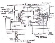
jkeny said:I'm currently using a CCS on the input diff amp stage of the "baby Huey" as per schematic. Is there any other biasing that could be used here? Shoog's LED quasi CCS for instance?
Shoog beat me to it with a short explanation. Here's the long version: Shoog's set up is not a quasi CCS. The LED is a voltage source. The added current is there to keep the LED in a steeper portion of the voltage/current slope, but it's still a constant voltage source, and it lets the AC component of the signal right on through. You need the AC component in the LTP so that when current in one side swings up, the other swings down, with the total remaining constant. With a voltage source there, the second section won't know what the first section is doing and will just sit there.
You can use a resistor instead of the CCS. But, if you want to preserve gain and low distortion in that stage you need a high value resistor, which means a high voltage negative supply.
jkeny said:I'm currently using Battery bias on ECL86 O/P stage - one 9V alkaline for all 4 tubes - should I change this to a bettery for each tube and should each battery have a cap accross terminals?What size cap?
John
You mean you are using fixed bias (connected to the grid), with a battery as a bias source? You will have some interaction between signals with a single battery. Don't know if you'd hear the difference, though. Try it with batteries for each tube and see.
Batteries do make some noise when producing current, but if used as a voltage source for fixed bias, the current is low, so I'd guess that the noise is low too. If you wanted to try bypassing with a cap, I'd try something like a 0.1-1uf film cap and see if you can hear any difference.
Sheldon
Shoog's set up is not a quasi CCS. The LED is a voltage source.
The reason I described it as a quasi CCS is because I have the voltage divided with a relatively high value resistor (330R I think), this should keep the overall current through the divider stable hence quasi CCS. I also have a small 47uf cap across the LED to try to stabilize the current a bit more. Hope that clears my point up.
Shoog
When I say I'm using Battery bias I mean on the cathode, + pole connected to cathode - pole to earth, giving about 9V at the cathode although I measure 12.5V here (I know I should use rechargeable battery) - I wonder should I use 12V SLA here?
John
John
Shoog said:
The reason I described it as a quasi CCS is because I have the voltage divided with a relatively high value resistor (330R I think), this should keep the overall current through the divider stable hence quasi CCS. I also have a small 47uf cap across the LED to try to stabilize the current a bit more. Hope that clears my point up.
Shoog
Sorry for the confusion. Your point was clear. I was referring to John's use of the the phrase "Shoog's LED quasi CCS". In the context of that post, I thought that maybe he had intrepreted the entire construct as a type of CCS. Wanted to make it clear that the nature of the LED bias was not fundamentally changed from being strictly a voltage source.
jkeny said:When I say I'm using Battery bias I mean on the cathode, + pole connected to cathode - pole to earth, giving about 9V at the cathode although I measure 12.5V here (I know I should use rechargeable battery) - I wonder should I use 12V SLA here?
John
Hmm, I doubt that an alkaline battery likes much current trickling through it at full charge. The fact that you are measuring a voltage well in excess of a fully charged battery seems like an indication of potential problems. You'd probably be ok, current wise, with a large enough SLA (you'd have to check some technical sources for for acceptable current trickle charging. I think a 12V SLA would give somewhere near 14V with a full charge trickle current. I think NiCad batteries also will tolerate a constant trickle charge.
Sheldon
Hey k, I'm busy with a circuit with 9v cell on cathode too... busy faulttraceing, I realised I connected the cells the wrong way around... hope I didn't kil the tube..... there was only like 9v on the annode too - ecc88 + opamp output stage
Thanks Sheldon,
When you say
John
When you say
do you mean that there may be a problem with the circuit or just that 12.5V is too much for the 9V battery?The fact that you are measuring a voltage well in excess of a fully charged battery seems like an indication of potential problems
John
Success at last... now one more step, replace the lm358 i used for setup, with something not so harsh.
llokie here for a css idea
My version uses 9v cell in stead of the css (which i will test tommorrow), and lm317 on anode set for 9v.
llokie here for a css idea
An externally hosted image should be here but it was not working when we last tested it.
My version uses 9v cell in stead of the css (which i will test tommorrow), and lm317 on anode set for 9v.
- Status
- Not open for further replies.
- Home
- Amplifiers
- Tubes / Valves
- All the Bias options