Many ... many ... many moons ago, I adapted the Nelson Pass` Aleph circuit topology to build a nifty, but ridiculously overbuild headphone amplifier that I named the Aleph H. I thought it was pretty cool, and circumstances came about that presented the opportunity to have my DIY project reviewed by Srajan Ebaen of 6Moons. Turns out Srajan liked it too and gave it a very positive review.
Somehow, I just never got around to publishing the schematic here for others to use. Periodically through the years I have had pokes from diyAudio members who have read the review and want to build my version, given its reviewed and 6Moons approved status. I have always shared with those that asked, but stupidly never taken the extra few moments to post it here.
That laziness ends here!
I have finally attached the schematic for the ciruit I built.
A couple of important notes:
1) The component numbers in my schematic DO NOT MATCH with the component numbers for the Aleph-Mini group buy boards. Be careful to ensure the right components end up in the right circuit locations.
2) All resistors are 0.25W rated except for the ones labelled in my schematic as R22, R23, R29 and R35, which are 3W rated.
Please forgive my excessive tardiness, and hopefully those who buikld this circuit will enjoy it as much as I do.
Attachments
If you search for thread by jwb with headphone in the thread title you can find a variant with JFET inputs. I was trying to keep more in line with Nelson's original designs, and also was avoiding using "unobtainium" parts. That being said, now that the LSJ74's are for sale here I am certainly tempted.
Unfortunately I don't have much in the way of measurement equipment, so no distortion graphs or numbers.
Unfortunately I don't have much in the way of measurement equipment, so no distortion graphs or numbers.
I remember that article ; so , for our amusement , here it is :
6moons audio reviews: Reality Check with Terry Aben
howeer , I was always puzzled - why you didn't change name of the article to , say , Mini H Aleph with Maxi Screw

6moons audio reviews: Reality Check with Terry Aben
howeer , I was always puzzled - why you didn't change name of the article to , say , Mini H Aleph with Maxi Screw
another question - in article , amp was rated as unity gain ;
so , please , clarify - what's more preferred by you - unity gain , or 10V/V , as in sch enclosed in your opening post ?
so , please , clarify - what's more preferred by you - unity gain , or 10V/V , as in sch enclosed in your opening post ?

Metalman, great work!
It seems that you run the Aleph H at a "high" (subjectively) biased current.
Have you experimented with other biased current values?
Why do you choose the present value?
It seems that you run the Aleph H at a "high" (subjectively) biased current.
Have you experimented with other biased current values?
Why do you choose the present value?
Is there a reason why R4,R5 have such low values? Other mini-Aleph circuits show these as 100k or 221k.
Last edited:
gain is R7/R5 in SE
in fact , R5 is redundant - R3 is there ...... as is for balanced , grounded for SE
in fact , R5 is redundant - R3 is there ...... as is for balanced , grounded for SE
I have a question... I have a couple of the mini aleph boards and I was planning on making those into a mini aleph's but sine this came up, I was thinking mini H instead. I do need a nice headphone amplifier anyway.
Problem I am having is when I look at the schematic, at the pictures I the 6moons review, and then at the boards -- where in the schematic are Q7 and Q8 (mostly because the schematic goes from Q6 to Q9)?
In the pictures in the review, Q7 looks populated by something, but I am not sure what it might be exactly. Just a lot confused by this and anyone know what this might be? Or am I missing something?
I am 99% sure this PCB and schematic match. Are these the boards you are using?
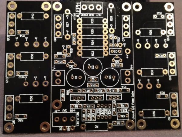
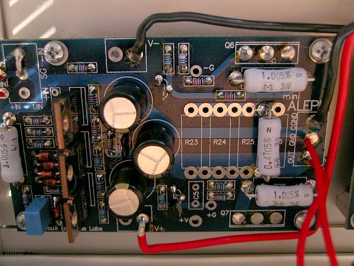
In this photo you can assume the output transistors (Q6, Q7) are tucked under the PCB to make room for layout issues.
An externally hosted image should be here but it was not working when we last tested it.
In this photo you can assume the output transistors (Q6, Q7) are tucked under the PCB to make room for layout issues.
Yep, those are the same BrianGT boards I've got with a "0711" written on the snap off power boards.
I am just not really getting it fully, because even when I compare metalman's schemattic to the one you posted, yours has the Q7 and Q8 in the diagram. I am not all that engineering minded, but I can follow a schematic with a relative moderate degree of difficulty. But what am I missing when I look at the two?
Yours is two channel? But then if I follow Q3, yours will lead to R4 and R5 then ground, while matalman's leads to R12 and R13 then ground.
I am sorry to ask all this, but I am sitting here just really, really confused.
You keep saying "Q8"... That's on a snap-off board. Is that the right number?
Q3 is the active component of the Constant Current Source that feeds power to the input preamp diff. pair, Q1/Q2.
Good advice. The PCB you have matches the schematic I posted - so now all you need to do is substitute the Aleph H values into the proper places on your PCB. Easy.
Do you skype? Check your PM.
Q3 is the active component of the Constant Current Source that feeds power to the input preamp diff. pair, Q1/Q2.
metalman said:1) The component numbers in my schematic DO NOT MATCH with the component numbers for the Aleph-Mini group buy boards. Be careful to ensure the right components end up in the right circuit locations.
Good advice. The PCB you have matches the schematic I posted - so now all you need to do is substitute the Aleph H values into the proper places on your PCB. Easy.
Do you skype? Check your PM.
Oh geez... I read that originally way back when metalman posted it, but totally forgot about it since then.
Thanks for pointing that out to me again.
I'll take another look with pen and pencil in hand and try to go from there. Thanks again 6L6.
Thanks for pointing that out to me again.
I'll take another look with pen and pencil in hand and try to go from there. Thanks again 6L6.
Lots of questions before starting the build.
Hi!
Today am using a modified “lovely cube”, a really good Lehmann Black Cube Linear Clone. It´s really fantastic, but lacks a little bit of soul. I noticed that if I reduced the feedback of the opamp the amp comes to life. My idea is to get rid if the opamps and heavy feedback entirety and get a little more back to basics.
Therefore I’m looking for a good simple single ended design without a huge amount of feedback to drive my 300Ohms sennheisers and this looks like it fits the bill. Has someone tried it out? It it as good as the &moons review suggest? Is there any similar simple design that performs considerably better?
Before I start out I have some questions:
-Am I correct in my assumption that only Q1 and Q2 need to be matched?
-Is there any good substitute for the ZTX450 in this application? Bc550?
-I would really need higher input impedance for my application. Can I make R4 a higher value, lets say 100K as in other aleph mini designs as in post #14? Is the single ended gain set by R8 and R4?
- In the pictures from the 6moons review the transformer seems to be 15v and I will give 21v rectified. The schematics says 15v. Will it be ok to run it at 15-16v rectified?
-Is there any suitable PCB designs available so I can make my own PCB?
Thanks for sharing the design!
Best Regards Christian
Christian,
Go to this website - Order | Chipamp.com
Scroll to the bottom and look for "ALEPH-TH-PCB" and "ALEPH-PS-PCB" -- those are the circuit boards in this project.
BC550 is a good substitue - but check the pinout, it is different from the ZTX
Go to this website - Order | Chipamp.com
Scroll to the bottom and look for "ALEPH-TH-PCB" and "ALEPH-PS-PCB" -- those are the circuit boards in this project.
BC550 is a good substitue - but check the pinout, it is different from the ZTX
- Home
- Amplifiers
- Pass Labs
- Aleph H Schematic - Revealed at Last