Hi Guys,
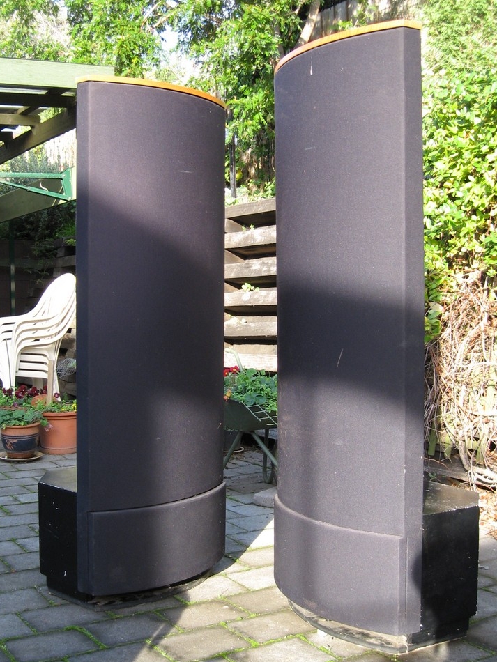
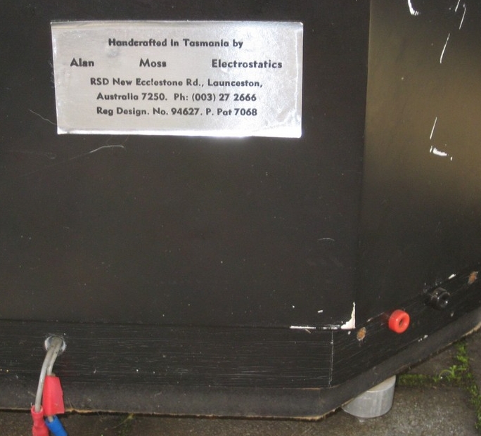
I have recently picked up a pair of Alan Moss ESLs.
There was a previous post way back on this forum about them....
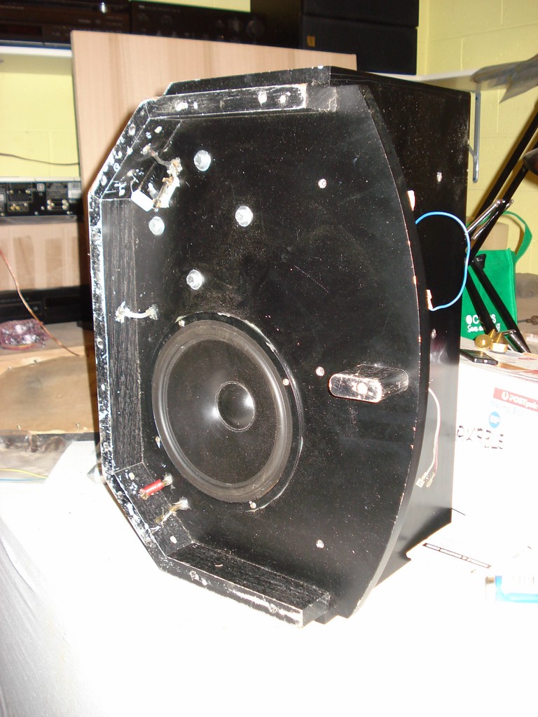
Well they are in pretty good nick really. Both bass drivers are excellent and one ESL is excellent.
The second one not so.
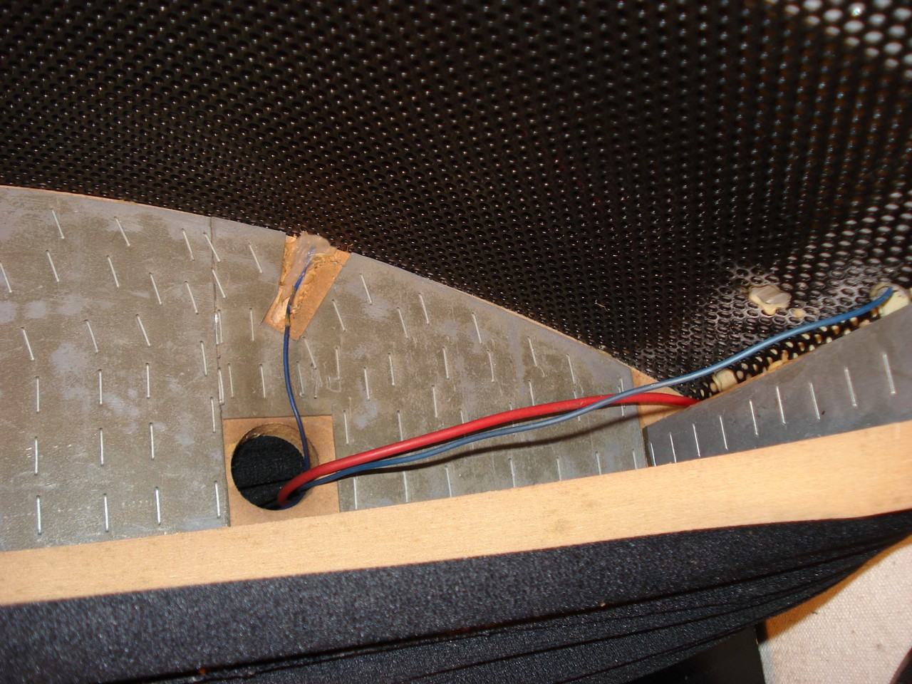
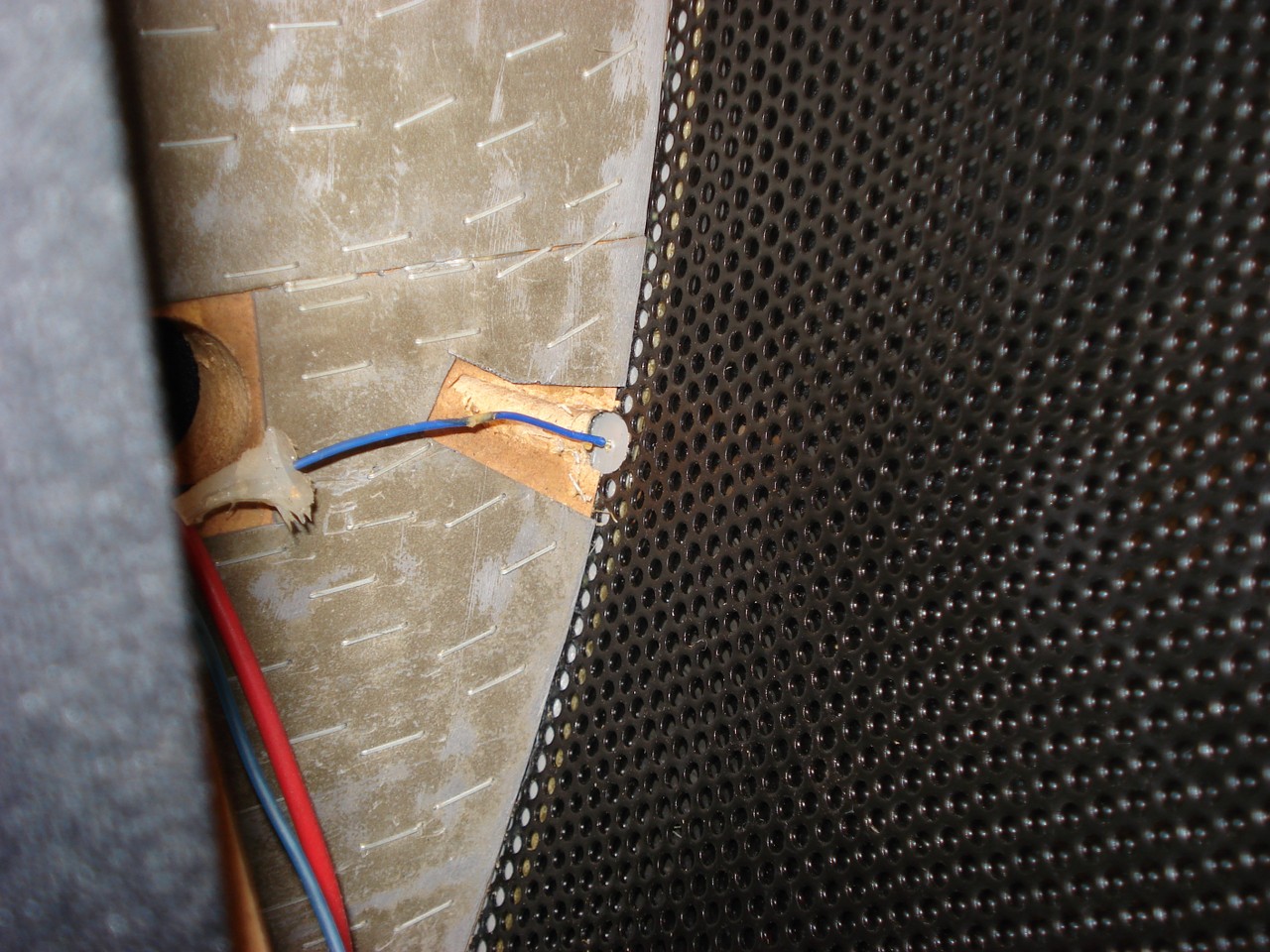
I have tracked down the fault to the connection of the HV bias to the Mylar diaphram. Has anyone had any experience with these speakers?
I am loath to pull them apart without checking whether somone else here has done it before.
I look forward to any replies.
Other pics to follow......
Matt
I have recently picked up a pair of Alan Moss ESLs.
There was a previous post way back on this forum about them....
Well they are in pretty good nick really. Both bass drivers are excellent and one ESL is excellent.
The second one not so.
I have tracked down the fault to the connection of the HV bias to the Mylar diaphram. Has anyone had any experience with these speakers?
I am loath to pull them apart without checking whether somone else here has done it before.
I look forward to any replies.
Other pics to follow......
Matt
An externally hosted image should be here but it was not working when we last tested it.
An externally hosted image should be here but it was not working when we last tested it.
An externally hosted image should be here but it was not working when we last tested it.
An externally hosted image should be here but it was not working when we last tested it.
An externally hosted image should be here but it was not working when we last tested it.
An externally hosted image should be here but it was not working when we last tested it.
An externally hosted image should be here but it was not working when we last tested it.
An externally hosted image should be here but it was not working when we last tested it.
Hi,
really beautiful? The build quality seems rather poor to me. Your HPs look much more professional.
jauu
Calvin
really beautiful? The build quality seems rather poor to me. Your HPs look much more professional.
jauu
Calvin
Hi Matt
Alan Moss is a very good friend of mine.
I had the pleasure I spending many hundreds of hours in front of those loudspeakers at his Riverside home.
You are very lucky to have a pair of those loudspeakers.
I can put you in contact with Allan if you like and he can help you
very likely to fix them.
Alan Moss is a very good friend of mine.
I had the pleasure I spending many hundreds of hours in front of those loudspeakers at his Riverside home.
You are very lucky to have a pair of those loudspeakers.
I can put you in contact with Allan if you like and he can help you
very likely to fix them.
No Sound from a Moss Panel?
Hi Matt
Alan is quite elderly now, long retired from the business and I believe not well. I also have a pair, which had what sounds like the same problem.
I didnt fix them, as I was a tad wary and knew a technician who has worked on ESLs here in Melbourne. I have these notes on the treatment, and some clarifying emails:
* NO SOUND FROM A MOSS PANEL *
It is very unlikely to be a UHT power supply problem (it never happened in over 15 years). What is most likely is that the contact with the membrane has been lost. This happened with one of the panels and a repair performed.
If it is with this panel the problem has occurred, then just relocating the wire, foil and foam to a slightly different position will regain membrane contact.
But if it’s with the other panel, here is what to do:
TESTING
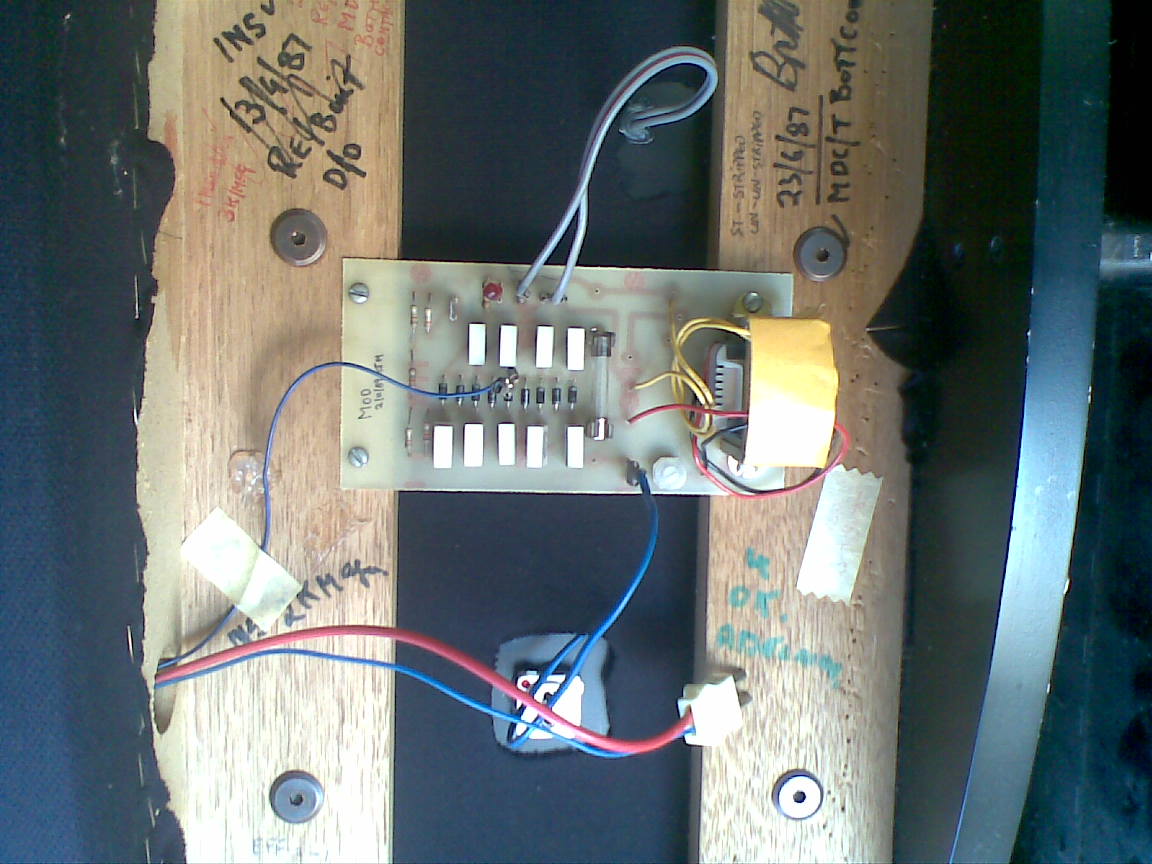
1. On the UHT board, locate the thin blue wire connecting to the membrane. It connects to a strip at the bottom left of the panel.
2. Solder another thin wire to that point on the UHT board.
3. Strip a very small section of the insulation away from the other end.
4. Poke the wire through one of the perforations on the front metal grid stator, so it just touches the membrane (take care not to perforate the membrane and have very little bare wire exposed or there will be sparking as it shorts with that front metal).
If you now get music, the fault is with the contact strip to the membrane.
THE REPAIR
1. Remove the cloth cover completely and disconnect the mains, or unplug the power pack.
2. Remove the black cloth tape along the right side and across the front of the panel (purchase some more wide tape as this will need to be replaced)
3. Carefully lift up the front perforated metal at the bottom right, so you can slip in the items listed below.
I did cut out portion of the front stator on the panel I repaired, but later found this was not necessary if you follow these 3 steps - but it is an alternative to gain access to the membrane.
4. The aim is to duplicate the metal strip contact, which has become corroded and lost conductivity to the membrane. Just placing a wire there is no permanent cure (tried that).
What is needed are
1. a wire bared at the end as in the test above
2. a piece of al foil to rest on top of the bared wire, to give a greater contact area,
3. a thin piece of foam to act as insulation between the aluminium foil and the front metal grid, and provide some pressure to secure the wire and foil with contact to the membrane, when it is all put back together again.
5. Slide the wire, foil and foam into the bottom right of the panel between the front perforated metal stator and the membrane.
6. Reconnect the power and be prepared to experiment with foam thickness. Too thin and the wire and foil will not make good contact with the membrane. Too thick and the membrane will be pushed to the rear stator so it shorts out.
7. When the correct foam thickness has been discovered, press the front metal stator back and secure with black cloth tape at the sides and front
8. Reinstall the cloth cover
> I gather the membrane is internal, and the stator is internal; to be certain: which colour
is the membrane?
No, not quite. The stator is the external metal mesh you can see and touch on the outside.
There is another similar Stator (but with different charge) constituting the metal mesh on the back. The setup is
• METAL STATOR (on the front)
• plastic metal coated membrane (in the middle)
• METAL STATOR (on the back)
> black cloth tape?
Hardware shops carry it. Get the widest cloth tape available - 5 cm should do, but more would be helpful. To ensure the tape sticks firmly, it might be a good idea clean gunk off the area you are going to tape with methylated spirits.
Another thought - if the faulty speaker is the one I repaired previously, it might be that the tape cloth I put on has lost its grip and so the tension on the foam etc has been reduced -> loss of contact with the membrane. Not likely, but just a thought
> If or when you are talking to Alan, if he has a copy of the EHT circuit diagram, that would be much appreciated.
I'll see what I can do, but Alan is a bit strange about "giving away trade secrets"
A couple of other things -
1. Use soft foam plastic for the repair - it will give you more flexibility in getting the best usable thickness
2. On the made up EHT board I have no idea what the bias setting would or should be.
I suggest that the screw be set in the middle. Adjust it until you hear a crackling in the membrane and back it off from that. Similarly with that board I made up - I did not check the setting on that either.
Adjust the bias to bring sensitivity to be the same for both speakers.
Before finally putting on the grill cloth, use a cardboard tube (used for posting rolled up items) as an ear trumpet to locate exactly where any buzzing problem could be happening.
This buzzing could be due to one of two causes -
(i) a particle of gunk has entered through the stator and is touching the membrane - cure is to vacuum the front to suck it out before putting back the cloth
(ii) a small section of the membrane has become fatigued and is moving too freely so it is touching the stator - cure is to inject a small amount of Silastic through the front. This has already been done in places and could be contributing a relative drop in sensitivity to one speaker over the other.
I hope this helps.
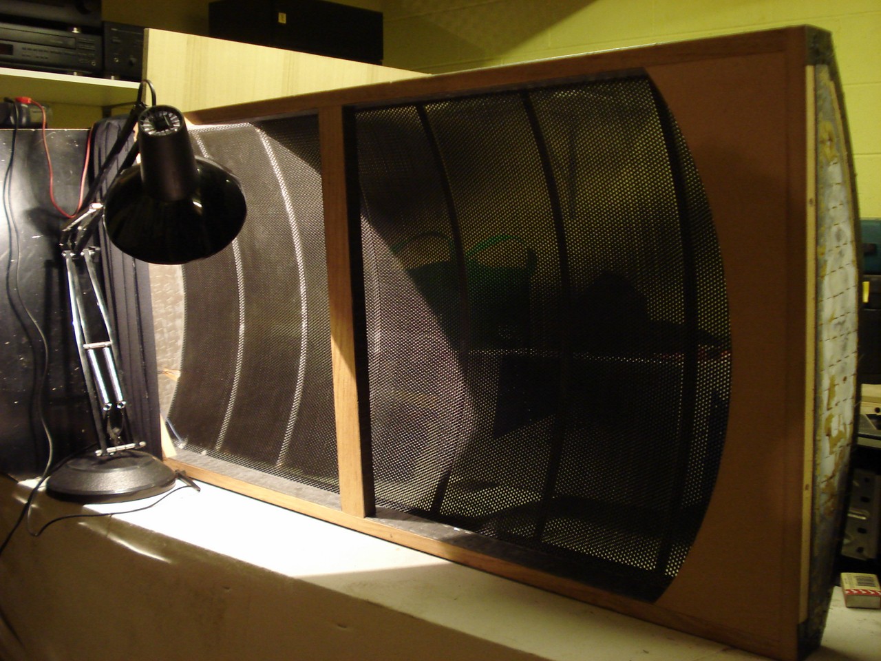
They dont have a great finish, but with their curved wide panels, I found they have a much wider dipersion pattern than many 'stats.
🙂
Cheers
Hi Matt
Alan is quite elderly now, long retired from the business and I believe not well. I also have a pair, which had what sounds like the same problem.
I didnt fix them, as I was a tad wary and knew a technician who has worked on ESLs here in Melbourne. I have these notes on the treatment, and some clarifying emails:
* NO SOUND FROM A MOSS PANEL *
It is very unlikely to be a UHT power supply problem (it never happened in over 15 years). What is most likely is that the contact with the membrane has been lost. This happened with one of the panels and a repair performed.
If it is with this panel the problem has occurred, then just relocating the wire, foil and foam to a slightly different position will regain membrane contact.
But if it’s with the other panel, here is what to do:
TESTING
1. On the UHT board, locate the thin blue wire connecting to the membrane. It connects to a strip at the bottom left of the panel.
2. Solder another thin wire to that point on the UHT board.
3. Strip a very small section of the insulation away from the other end.
4. Poke the wire through one of the perforations on the front metal grid stator, so it just touches the membrane (take care not to perforate the membrane and have very little bare wire exposed or there will be sparking as it shorts with that front metal).
If you now get music, the fault is with the contact strip to the membrane.
THE REPAIR
1. Remove the cloth cover completely and disconnect the mains, or unplug the power pack.
2. Remove the black cloth tape along the right side and across the front of the panel (purchase some more wide tape as this will need to be replaced)
3. Carefully lift up the front perforated metal at the bottom right, so you can slip in the items listed below.
I did cut out portion of the front stator on the panel I repaired, but later found this was not necessary if you follow these 3 steps - but it is an alternative to gain access to the membrane.
4. The aim is to duplicate the metal strip contact, which has become corroded and lost conductivity to the membrane. Just placing a wire there is no permanent cure (tried that).
What is needed are
1. a wire bared at the end as in the test above
2. a piece of al foil to rest on top of the bared wire, to give a greater contact area,
3. a thin piece of foam to act as insulation between the aluminium foil and the front metal grid, and provide some pressure to secure the wire and foil with contact to the membrane, when it is all put back together again.
5. Slide the wire, foil and foam into the bottom right of the panel between the front perforated metal stator and the membrane.
6. Reconnect the power and be prepared to experiment with foam thickness. Too thin and the wire and foil will not make good contact with the membrane. Too thick and the membrane will be pushed to the rear stator so it shorts out.
7. When the correct foam thickness has been discovered, press the front metal stator back and secure with black cloth tape at the sides and front
8. Reinstall the cloth cover
> I gather the membrane is internal, and the stator is internal; to be certain: which colour
is the membrane?
No, not quite. The stator is the external metal mesh you can see and touch on the outside.
There is another similar Stator (but with different charge) constituting the metal mesh on the back. The setup is
• METAL STATOR (on the front)
• plastic metal coated membrane (in the middle)
• METAL STATOR (on the back)
> black cloth tape?
Hardware shops carry it. Get the widest cloth tape available - 5 cm should do, but more would be helpful. To ensure the tape sticks firmly, it might be a good idea clean gunk off the area you are going to tape with methylated spirits.
Another thought - if the faulty speaker is the one I repaired previously, it might be that the tape cloth I put on has lost its grip and so the tension on the foam etc has been reduced -> loss of contact with the membrane. Not likely, but just a thought
> If or when you are talking to Alan, if he has a copy of the EHT circuit diagram, that would be much appreciated.
I'll see what I can do, but Alan is a bit strange about "giving away trade secrets"
A couple of other things -
1. Use soft foam plastic for the repair - it will give you more flexibility in getting the best usable thickness
2. On the made up EHT board I have no idea what the bias setting would or should be.
I suggest that the screw be set in the middle. Adjust it until you hear a crackling in the membrane and back it off from that. Similarly with that board I made up - I did not check the setting on that either.
Adjust the bias to bring sensitivity to be the same for both speakers.
Before finally putting on the grill cloth, use a cardboard tube (used for posting rolled up items) as an ear trumpet to locate exactly where any buzzing problem could be happening.
This buzzing could be due to one of two causes -
(i) a particle of gunk has entered through the stator and is touching the membrane - cure is to vacuum the front to suck it out before putting back the cloth
(ii) a small section of the membrane has become fatigued and is moving too freely so it is touching the stator - cure is to inject a small amount of Silastic through the front. This has already been done in places and could be contributing a relative drop in sensitivity to one speaker over the other.
I hope this helps.
They dont have a great finish, but with their curved wide panels, I found they have a much wider dipersion pattern than many 'stats.
🙂
Cheers
What a fantastic reply!
Thankyou.
I will have a crack at the repair as I am pretty sure that it is the connection to the diaphram.
Do you know whether Alan is still in contact with anyone on this forum?
I also live it Tassie and it would be a shame not to have a few people that can rebuild/repair these panels.
Also mine did not come with any crossovers. Do you have any information on the type and crossover frequencies that are used?
Cheers
Matthew
Matt
I think you might have missed my post, I was with Allan when he was designing the very speakers you have.
The panels where crossed over at around 100hz
The panels by default from memory rolled off naturally at that frequency. I can phone and and have a talk with him, to verify my comments.🙂
What part of Tassie are you from?
Hi Anthony
Are you sure the XO was as low as 100 Hz?
Tho' they are biggish panels
Were there different models??
Thanks
Are you sure the XO was as low as 100 Hz?
Tho' they are biggish panels
Were there different models??
Thanks
Hi otto
Yes I am quite sure they rolled off at that frequency.
They were a number of models made of these panels.
The ones that matt have were the standard issue so to speak.
There was also a 2/3 height version of the main production models.
Long before Alan intergrated the sub woofer with the panels we use to listen to much larger panels, from memory they were over 6 feet in height and sounded quite excellent without any sub.
The sub of course added that extra depth to the bottom end.
A few times we visited a chap named John Coulson in Dilston.
He had a pair of the 12 foot models, 2 x 6 foot panels stacked on top of each other like totem poles, with a pair of very large transmission line subs sitting behind each set of panels.
Alan also use to make heaps of amplifiers to drive these panels, ranging from OTL valve amps to MOSFET SS and MOSFET/Valve hybrid amps and we got to listen to quite a number of high end commercial amplifiers borrowed from a number of Audiophiles and shops around Australia.
Matt before you attempt any repairs be sure that the voltage multiplier is working OK, it should be putting out around 3kv so you will need a high voltage probe connected to your multimeter to check it safely. Does the red LED light up on the Multiplier board?
Anyway I hope this helps.
🙂
Hi Anthony
How is Alan lately?
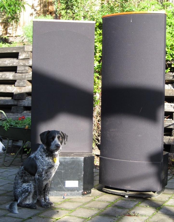
(Though I live in Melbourne) I bought mine from John Coulson a while back, but due to moving houses haven't set them up (their height is c 1550 mm).
As you know, stats can be hard to drive:
what minimum ohms do you think they are, and for a typical listening distance, for these what watts range would you recommend?
Cheers
How is Alan lately?
(Though I live in Melbourne) I bought mine from John Coulson a while back, but due to moving houses haven't set them up (their height is c 1550 mm).
As you know, stats can be hard to drive:
what minimum ohms do you think they are, and for a typical listening distance, for these what watts range would you recommend?
Cheers
best bass
This I think would be streets ahead of the bass in the ESLs (or any other bass), esp to match the dipole radiation of the ESLs:
http://www.gr-research.com/index.asp?PageAction=VIEWPROD&ProdID=140
http://www.audiocircle.com/index.php?topic=54875.0
This I think would be streets ahead of the bass in the ESLs (or any other bass), esp to match the dipole radiation of the ESLs:
http://www.gr-research.com/index.asp?PageAction=VIEWPROD&ProdID=140
http://www.audiocircle.com/index.php?topic=54875.0
Ah! it's driving me nuts! how do they curve the diaphragm like that? It's voodoo I tell you. martin logan dose the same thing.
Hi,
well one could argue about best bass. 😉
The 100Hz rolloff implies that the high-Q resonance of the panel is ´used´ within the bandwidth of the panel. Electrically the panel is crossed over with a high-Q highpass filter at a bit higher freq than the resonance freq. ML used to use this technique too. This gives a very linear response and best efficiency, but the sonic fingerprint of the long decay of the resonance is clearly audible and disturbing.
So most designers cross over the panels well above the resonance freq. With curved panels You shouldn´t go much lower than app 200Hz or You seriously sacrifice on efficiency. Doing so You have to match the radiation character of panel and bass. God integration of panel and bass is not a matter of how the bass is driven. Passive, active, or active servo doesn´t play the major role here. Using rather thin and tall panels a similar radiation patern can only be achieved with basses radiating in a dipolar fashion.
Since the requirements for high dynamics increase considerably the lower the frequency goes and the larger the room is, a ´real SUB´-woofer should be added because this is where the dipole bass suffers. The different radiation pattern doesn´t play a big role anymore, so You can use basically any type of bass You like.
Two fine examples of such different systems are the ML Statement and the Statement II. A two way system on one hand and a three way system with dipolar mid-bass on the other hand. I have no doubt that the II was the superior system, since I went the same way and omit the dedicated subwoofer only in small rooms. 😉
Servos are not really superior in the subcontra-octave freq-range apart from maybe reducing distortion levels. But they may react ´annoyed´ when overdriven, which might happen quite easy, because basses frequently work under high excursion level conditions. Just consider that the linearity and dynamics of a servoed sub depends on the linearity and dynamics of the sensor device in first place (talking about prob. 90-100dB of dynamic range!). Large excursions even at low freqs result in large acceleration values (several 100s of g!). It´s hard to find commercial sensor devices that can fulfill such stringent demands together with low weight and acceptable cost.
A well executed CB working below 60Hz will probabely work equally well with reduced complexity of the electronics and better large signal and overload handling. Concentrate on large membrane area and really good stiff compartment of the bass. 😉
jauu
Calvin.
Hi otto
The panels dipped down to around 1.5 ohms, I cannot remember
at what frequency I would have to ask Alan.
We had MOSFETs amplifiers as low as 60 watts driving the panels to good listening levels before the usual cracking from the panels when the amp clipped.
I had one of my very early 800 watt amplifiers running the panels at one time and one of Alan's comments was he had never hear the ESLs goto such high sound pressure levels without cracking.
So the short answer to your question would be get the most powerful best sounding amplifier you can get your hands on that can drive low ohms levels.
Try around 200-300 watts RMS @ 4 ohm Amplifier would drive them just fine, with a very generous high current power supply.
I heard some of Alan's 60 watt OTL valve amps drive them very well
As well as a 5 watt SE valve, it really depends how well the amplifier is designed, not so much the power output that matters with ESLs
Thanks Anthony
1.5 ohms? I carumba!
That is rather testing – would I think eliminate 80%? of amps . .
A high current power supply – (just what eg Apogee ribbons like). Could you suggest some ballpark values for how generous – say a minimum, and a desirable value?
Thanks
1.5 ohms? I carumba!
That is rather testing – would I think eliminate 80%? of amps . .
A high current power supply – (just what eg Apogee ribbons like). Could you suggest some ballpark values for how generous – say a minimum, and a desirable value?
Thanks
Hi Anthony,
Clearly I missed your post 🙂
It would be great to get in contact with Alan.
What is the best way of contacting you?
I am in Hobart.
Matt
Clearly I missed your post 🙂
It would be great to get in contact with Alan.
What is the best way of contacting you?
I am in Hobart.
Matt
Hi otto
The 1.5 ohms is not across the whole frequency spectrum, from memory
most of the time it is somewhat higher, Alan did place a 10 watt low ohm resistor in line with the power transformer to give less capable amps an easier time, it seemed to work.
As far as a power supply goes, ball park would be twice what you would need at 4 ohm load, if you are using say a 500va transformer go for an 800VA transfomer.
Hi Matt I have a contact phone number on my web site in the Contact page, give me a call tomorrow and we can have a talk.
Hi Otto, the 1.5 ohm is not unusual, and often occurs higher up in the spectrum. A series resistor can help. As for the amp, my Lifeforce by AKSA does very well with my ESLs with a similar impedance pattern and phase shift. If Hugh's amps don't suit, there are some Class D designs that have done well reportedly. Hypex being one of them.
- Status
- Not open for further replies.
- Home
- Loudspeakers
- Planars & Exotics
- Alan Moss ESLs