I at last built up my Akido line preamp and compared input tubes-12AX7 and 12AT7, using 12AU7 for low impedance output to drive a single EL34 to about 8watts.
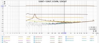
With a 12AX7 input tube, the gain is about 24x but max input is about 0.5v (12v out) before the distortion increases rapidly.
With a 12AT7 it's half so 1v in = 12v out before the 2nd harmonic starts to ezceed 1%.
The HT is 200v from a PS21 regulated power supply. I am waiting for parts to finish the output stage so can't audition it just yet.
With either tube, 2nd harmonic distortion predominates. (there is no global feedback)
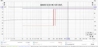
But I can't explain the phase shifts - from +180 to -180 instantly, with the frequency of the switch varying with input level and tube type.
I suspect it's something to do with the Akido's noise and hum cancellation design.

Any thoughts?

With a 12AX7 input tube, the gain is about 24x but max input is about 0.5v (12v out) before the distortion increases rapidly.
With a 12AT7 it's half so 1v in = 12v out before the 2nd harmonic starts to ezceed 1%.
The HT is 200v from a PS21 regulated power supply. I am waiting for parts to finish the output stage so can't audition it just yet.
With either tube, 2nd harmonic distortion predominates. (there is no global feedback)
But I can't explain the phase shifts - from +180 to -180 instantly, with the frequency of the switch varying with input level and tube type.
I suspect it's something to do with the Akido's noise and hum cancellation design.

Any thoughts?

I've not had anything similar when measuring the old SE amp, nor 2 MF X10 clones nor solid state amps.
I disconnected the power supply feed capacitor to the lower triode of the output 12AU7 but this did not have any effect, so it's still a mystery.
I'll put it down to, as you suggest, a measurement artifact.
Quick question if I may? What would a single EL34 UL connected need for 8watts into 8r (8v RMS) - ball park? Cathode was at 19v / 70ma / 270r on the original amp. (guessing that I have about 35v p-p before the grid goes positive = ~12.5v RMS)
Since the bias is 19V you need 19V peak drive for 'full' output. This is presumably close to 8 Watts, depending on your transformer impedance.
Made a few mods -
Removed the HT dropper resistor so HT is now 217 instead of 204v.
Fitted a 12AT7 for the input and 12AU7 for the output. (reduced the input tube cathiode resistor from 2k to 330r.) Gain is 12x, compared to 24x with a
12AX7.
Rearranged the mains wiring.
Used a better RCA input lead. (I found out that the budget Amazon ones are not properly screen).
At 1.3v RMs in 15v RMS out 2H is 1.1%, 3H is 0.13%
At 50mv in, 2H is .049% and the higher harmonics are lost in the noise at 0.055%
Still have the strange measurement phase effect of an apparent 360degrees shift which doesn't happen if I do a loopback test.