Hi,
Hope someone can help, The relay is not kicking in on my aiwa p22, I have checked the center voltage (TP1 & tp2 =0V) and idle current and they are stable. I have no DC at the output stage. The RY1 coil is reading 620 ohms resistance. I opened up the relay, connected some old headphones and manually pressed the relay to engage it and the sound seems fine. So it just looks like a relay driver. I took out SA750 (protect) transistor and its reading fine, (hfe=406), Diode D19 (ISI555) also reading ok in diode mode on voltmeter.
These are the voltages with respect to ground on IC3 (ta71317p)
pin1 = +0.65 (should be -0.75)
pin2=0 (no dc voltage detected)
pin3=0 (no dc voltage detected)
pin4=0 (ground =ok)
pin5= -0.8 (close should be -0.7)
pin6=8.8 (relay drive should be 1.5v)
pin7= 0 (no voltage given on schematic)
pin8=0 (should be 1.2v)
pin9= 3.3 (ok)
So pin 1, 6 & 8 look suspect (not sure about pin 7) anyone know what the voltage on this should be.
C23 is reading 27.6uf and the negative side has continuity to ground ok.
R55= 214k ohms
The only physical damaged component is R89 which is burned, Its right under the protect transistor mentioned about, but I can not determine the value from the copy of the schematic, also I can not read the color bands anymore. Its reading 18 ohms at present. Not sure where it connects to either.
Anyone with more experience with these? Or anyone with the original service manual, Thanks in advance.

Also the voltage at both ends of the relay coil =0.11v which leads me to believe Pin 6 measurement is wrong as this should be the same. Going to update in a few mins
Yes as suspect correction below
These are the voltages with respect to ground on IC3 (ta71317p)
pin1 = +0.65 (should be -0.75)
pin2=0 (no dc voltage detected)
pin3=0 (no dc voltage detected)
pin4=0 (ground =ok)
pin5= -0.8 (close should be -0.7)
pin6=0V (relay drive should be 1.5v)
pin7= 0 (no voltage given on schematic)
pin8=0 (should be 1.2v)
pin9= 3.3 (ok)
Ok read Q13
E=26.1
C=0.6
B=25.5
Now Q14
E=0V
C= (when reading voltage the relay kicked in, gave me some fright 🙂
Then after a few seconds it turns off. Hmm Getting closer
E=26.1
C=0.6
B=25.5
Now Q14
E=0V
C= (when reading voltage the relay kicked in, gave me some fright 🙂
Then after a few seconds it turns off. Hmm Getting closer
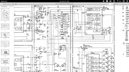
It's hard to make out from that diagram but Q14 appears to monitor current in the output stage via that power resistor to its left.
On that basis, and from what I can deduce you should be able to remove Q14 to eliminate any issue around there. The voltage across that resistor should be minimal in normal use.
See if pulling the transistor allows the relay to operate correctly.
On that basis, and from what I can deduce you should be able to remove Q14 to eliminate any issue around there. The voltage across that resistor should be minimal in normal use.
See if pulling the transistor allows the relay to operate correctly.
Yes very hard to make out, I have checked everywhere online to see if I could find a better schematic to no avail.
I removed Q14 and there is no change, I tested it while I had it out and its reading find hfe=440.
But did notice I was reading a wrong pin earlier on Q14.
The reading now is : E=26.3, C=1.1 and B=25.8 which is similar to Q13.
Q13=e=26.1, c=1.1, b=25.5
I checked for voltage on the coil again(measuring on the diode in parallel with it) and am reading 0V, but when I connect the front metal fascia to the main chassis again it goes upto 8.8V, checked it a few times, that is why I was getting this earlier, see above.
The fact that I am getting a positive voltage on pin 1 of IC3, Which somehow is coming from Q13 & 14( either from the collector or emitter--can not make this out as vital part missing), I wonder is this causing pin 6 and 8 to be off too?
Make sure your meter is firmly connected to ground.
Locate the two 47k resistors that go to pin 1. What voltage do you have on the ends that go to the two transistors?
What is the voltage on R94 (100k) that disappears off the bottom of the circuit?
Locate the two 47k resistors that go to pin 1. What voltage do you have on the ends that go to the two transistors?
What is the voltage on R94 (100k) that disappears off the bottom of the circuit?
Hi Mooly thanks for helping me out with this,
as requested (I also made temp earth connection between main chassis and front fascia that needed to be disconnected to take measurements)
R93 (reading 46k) continuity to pin 1 ok, also to the collector of Q13 is reading 0.63V
R51(reading 47.2k) goes to collector of Q14 continuity good at both ends reads 0.62V
R94 (reading 64k in circuit) continuity to pin 1 is ok, this also goes to D18(diode reading ok)
voltage reading 0.31 and 0.65v at pin 1 end
See new diagram R94 is going to anode of D18
Attachments
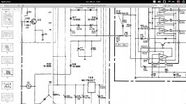
Have you got a negative voltage on that diode/cap ? It generates a negative rail and I would guess around -25 to -28 volts. That electrolytic (and diode) could be suspect.
Yes found my issue, I had already removed the bridge rectifier previously to test it and it tested ok. I checked and I had the -26v and the +26V at the bridge rectifier, I then checked the 3 cables coming from the transformer and there was 20V AC on both blue cables, these then went to a trip fuse CB1 & CB2 but there was a broken track on CB1 at the transformer end. Thanks so much for making me concentrate in this area, I presumed when I had the -26 & +26 rails power was ok🙂
With thanks to you, your always the first to respond here. Wish I had your electronic knowledge, I can take measurements and test most components, but my theory is lacking. Thanks all the way from Ireland.
Oh and a dodge schematic diagram does not help much either. Checked my idle current again and its bang on, listening to a cassette and warming it up to check it again.
Thanks for the kind words 🙂
(That extra negative rail with its small 10uF reservoir cap and 100k resistor across it is used to generate a rail that collapses very quickly on power off. That enables the relay driver to disconnect the speakers while the main rails are still collapsing)
(That extra negative rail with its small 10uF reservoir cap and 100k resistor across it is used to generate a rail that collapses very quickly on power off. That enables the relay driver to disconnect the speakers while the main rails are still collapsing)
- Status
- Not open for further replies.
- Home
- Amplifiers
- Solid State
- Aiwa SA-P22 mini compo relay issue