I have a modded Audio Innovations 500 where the extreme left tube is started overglowing. Changing tube makes no difference. Is it likely to be a capacitor leaking problem?
Last edited:
Check the voltage on the grids of the EL34s, pin 5. They should be almost equal in value. The cathodes, pins 1&8, should sit at around 28volts.If the grid is not at or around zero volts DC, check the coupling capacitor.
It tends to be faulty coupling capacitor letting dc through and upsetting grid voltage.
Or burned grid stopper which is unlikely.
Or cold soldered joint in grid circuit.
Or burned grid stopper which is unlikely.
Or cold soldered joint in grid circuit.
Well this one, sitting directly under the tube, seems pretty burned, so much that I cant read the original value.

Looks like it could do with refurbishing by the look of it.
Let me know which pin it connects to and I can work out what the value is for you.
Bottom right of your photo shows a discoloured component, I would check that one as well.
However that will be the result of a fault, not the cause.
Let me know which pin it connects to and I can work out what the value is for you.
Bottom right of your photo shows a discoloured component, I would check that one as well.
However that will be the result of a fault, not the cause.
Last edited:
That would mean between the plate and the control grid. Doesn't seem that likely...!
Best regards!
Best regards!
The pins read clockwise from underneath so if it was pins 6 & 4 that would be the screen grid supply resistor. Pin 6 has no connection in the valve so we used it as a tag to connect components to.
It is a 100R 2Watt resistor. That is definitely not a cause for red plating in a good valve! Check the control grid voltage, pin5, it should be around zero volts.
It is a 100R 2Watt resistor. That is definitely not a cause for red plating in a good valve! Check the control grid voltage, pin5, it should be around zero volts.
Well, it is pin 3 and 5, it's easy to see since they are numbered underneath. At the other side socket, its easier to read the numbers
An externally hosted image should be here but it was not working when we last tested it.
An externally hosted image should be here but it was not working when we last tested it.
That is not possible to go between pins 3 & 5 it is definitely on pins 4 & 6.
Replace the resistor and measure the grid voltage on pin 5.
CAUTION, there is a possible 350volts on pin 6!
Replace the resistor and measure the grid voltage on pin 5.
CAUTION, there is a possible 350volts on pin 6!
I dont know how you would count that otherwise than clockwise from after fitting slit of socket/tube. I am just reading the numbers pregnated on the pictured downside of the socket. As you can see on picture they are numbered 3 and 5, while 4 is the middel (bottom) one not connected with resistance. So you mean its a 100 ohms and not 1 k.ohms resistans?
Originally we fitted 100R some had 1k0. I prefer 1k0 but measure the others and fit the same.
The link of wire is between pins 8 & 1. so count clockwise from the right hand tag (pin1).
The link of wire is between pins 8 & 1. so count clockwise from the right hand tag (pin1).
It blows the 2,5A main fuse quite fast with that tube 4 inserted, so I have to measure fastly.
Please, what does FIR processing mean ?
Yeah the resistor burn is a consequens, when the tube is burned off. I cant really mesure voltages fast enough with tube inserted, cause it happens so fast. Just fired to more tubes and 2 resistors. So now I have to locate the coupling capasitor. What leg is it connected to?
Looks like leg and 1 and 8 (the joint ones) have to much voltage compared to the other chanel tube.
Your picture is not in focus. We cannot read the numbers either...
If they were connected to the cathodes (on pins 1 and 8), they were originally 100uF 100 volt caps. The big gold resistor was 220R originally too.
If they were connected to the cathodes (on pins 1 and 8), they were originally 100uF 100 volt caps. The big gold resistor was 220R originally too.
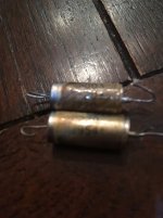
Makes sense. Yeah its those. Just when I messure one, it shows 58.9 uF and the broken ones show nothing=0.
Well, it is pin 3 and 5, it's easy to see since they are numbered underneath....
I have not followed the discussion to know what pins are in dispute.
However the molded numbers are sometimes confusing. Start from the fitting slot/tab. It is between pins 8 and 1. The molded "1" is near socket 1 but looks closer to socket 2. They should mold the numbers very close to the sockets. They didn't.
Attachments

To finish the tread: It was, as I suspected from the start, the 100uF capacitor at the picture/tubes that was not funtioning and caused the resistance, tubes and fuse to burn off. After replacing one capacitor 100uF/100V at each channel and the burned out restanses and the 2 Tubes at both channels, it's playing nicely again. Thanks to everybody, and especially Jon for the help. As I explained I am a high (Kilo-)Voltage electrician and not an electronic and tube amp qualified. Am Happy!!
Pleased to be of assistance. Enjoy your Audio Innovations Amplifier.
Just an aside, we had problems with a number of selector switches. These were the silver plated contact types, they got dirty and became noisy. Most were replaced under their warranty period but a few are still around. Choose the gold flashed contact type if you need to replace it.
Just an aside, we had problems with a number of selector switches. These were the silver plated contact types, they got dirty and became noisy. Most were replaced under their warranty period but a few are still around. Choose the gold flashed contact type if you need to replace it.
- Status
- Not open for further replies.
- Home
- Amplifiers
- Tubes / Valves
- AI500 1 tube overglow