So, long story short is that my Nakamichi AV-10 blew center channel power amp stage 5 years ago... in a big way - still stinky magic blue smoke and all.
5 difficult years pass and now I eventually recover property from the toxic ex that included this faulty and now redundant amp.
Frankly, I loathe the thought of a selling-on eBay experience, and have a more than sufficient Yamaha 7.1 now in service, so the decision was made to strip Naka down for bits, the intent to build and add an active sub-woofer to the (sub-jective) fun.
Honestly, bass isn't lacking from any of the speakers in this way oversize system in a small unit, but lets see.
Project uses:
Phonic PSW118 enclosure: Switchable phase and crossover, P Audio LF Driver "2241" (JBL type), 4" vented coil, ribbed cloth surround cone, 600w RMS @ 8 Ohms.
LJM L25 500W @ 4 Ohm - KTB817 KTD1047 2SA1186 2SC2837 assembled Mono Amp board. eg. http://www.ebay.com.au/sch/i.html?&_from=R40&_trksid=p4712.m570.l1313.TR0.TRC0.H0.TRS0&_nkw=111207981673
[possibly under size for Driver, but Driver is oversized for room and the 5" thick single concrete party wall between me and a little old somewhat deaf lady]
Also use of;
a) Forced draft cooling with no external heat sink fins at rear of Amp [subject to advice on locating Amp and PS inside speaker enclosure.... is amp board robust enough to last G forces in there?]
b) Speaker protection using uPC1237HA chip [and use of pin 1 for O/L]
c) basic gain control... 10k (B) pot.
d) possible upgrade of input Op amp and supply on power amp board.
So, easy enough to trace out the subject power circuit, but not easy to figure out the control logic here.
Likewise, I seek advise on best way to use these quality components in the sub-woofer project.
What I don't have is a full schematic of this Naka AV-10 Amp that would help me understand an unusual Transformer/power supply configuration and possible re-use of the good L/R power amp stage board [dead Center and good Surround channels are on a separate board, thankfully].
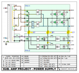
Attached is schematic of what I have traced out.
The transformer windings are drawn as constructed.
Board PS1-1 is identical to Naka circuit, with exception of addition of C2 [ 4700uF (M) / 80V ] caps. I reasoned they may as well be used.
Board PS1-2 is my attempt to use the 17V winding for 12V and/or 5V D.C. - Amp cooling fan and control.
A second transformer and rectifier/regulator board can be added to supply input stage op amp of the power amp module I have purchased, if such modification has merit. This is the subject of another thread.
The 'unusual' circuit I question is that of the relay switching of the 52v/0/52v [A1, A2] windings.
This transformer was used for L & R Front power amp board.
Incidentally, a 2nd smaller transformer was used for Center / Surround power amps. all main board Op amps, FM tuner, display panel, A/D converter board and video output. This transformer is around 75% the size of the big one I'm using.
An even smaller 3rd transformer was used for standby power and I think cooling fan supply.
Best I can figure by pcb tracing is that these relays (1 only shown as DP for clarity) are controlled, in part, by NTC thermistor mounted on power amp/s heatsink. Perhaps selection of A + B front speakers may have switched this in/out?
A full circuit schematic would help heaps in understanding whats going on here!
Anyhow;
a) Why would this higher voltage winding be switched in/out? Loading/unloading while in operational mode according to demand or thermal overload?
b) In using this transformer, should I just omit relay and use both A and B windings hard wired with their associated bridge rectifiers, or just use the higher voltage A1 and A2 set?
c) Is there any advantage to using both sets in terms of stability of transformer output? Is that why switched in/out?
Assuming the use of the 17V 'D' winding as shown in diagram;
d) Where is the recommended 0V bus-tie between the PS1-1 and PS1-2 0v rails between the circuit boards?
i.e. At location A or B or C, or at all... or not at all?
It would appear that this bus-tie between all 3 transformers of 0V rails be they dual +/- or single + to 0V was done at A + B + C in the AV-10, however, in D.C audio and RF power supply applications I'm not sure what is industry best practice for noise reduction.
....and, Folks, please advise any recommended changes to this power supply configuration. I suspect upgrade of the Q1 and perhaps Q2 bridge rectifiers would be wise.
5 difficult years pass and now I eventually recover property from the toxic ex that included this faulty and now redundant amp.
Frankly, I loathe the thought of a selling-on eBay experience, and have a more than sufficient Yamaha 7.1 now in service, so the decision was made to strip Naka down for bits, the intent to build and add an active sub-woofer to the (sub-jective) fun.
Honestly, bass isn't lacking from any of the speakers in this way oversize system in a small unit, but lets see.
Project uses:
Phonic PSW118 enclosure: Switchable phase and crossover, P Audio LF Driver "2241" (JBL type), 4" vented coil, ribbed cloth surround cone, 600w RMS @ 8 Ohms.
LJM L25 500W @ 4 Ohm - KTB817 KTD1047 2SA1186 2SC2837 assembled Mono Amp board. eg. http://www.ebay.com.au/sch/i.html?&_from=R40&_trksid=p4712.m570.l1313.TR0.TRC0.H0.TRS0&_nkw=111207981673
[possibly under size for Driver, but Driver is oversized for room and the 5" thick single concrete party wall between me and a little old somewhat deaf lady]
Also use of;
a) Forced draft cooling with no external heat sink fins at rear of Amp [subject to advice on locating Amp and PS inside speaker enclosure.... is amp board robust enough to last G forces in there?]
b) Speaker protection using uPC1237HA chip [and use of pin 1 for O/L]
c) basic gain control... 10k (B) pot.
d) possible upgrade of input Op amp and supply on power amp board.
So, easy enough to trace out the subject power circuit, but not easy to figure out the control logic here.
Likewise, I seek advise on best way to use these quality components in the sub-woofer project.
What I don't have is a full schematic of this Naka AV-10 Amp that would help me understand an unusual Transformer/power supply configuration and possible re-use of the good L/R power amp stage board [dead Center and good Surround channels are on a separate board, thankfully].
Attached is schematic of what I have traced out.
The transformer windings are drawn as constructed.
Board PS1-1 is identical to Naka circuit, with exception of addition of C2 [ 4700uF (M) / 80V ] caps. I reasoned they may as well be used.
Board PS1-2 is my attempt to use the 17V winding for 12V and/or 5V D.C. - Amp cooling fan and control.
A second transformer and rectifier/regulator board can be added to supply input stage op amp of the power amp module I have purchased, if such modification has merit. This is the subject of another thread.
The 'unusual' circuit I question is that of the relay switching of the 52v/0/52v [A1, A2] windings.
This transformer was used for L & R Front power amp board.
Incidentally, a 2nd smaller transformer was used for Center / Surround power amps. all main board Op amps, FM tuner, display panel, A/D converter board and video output. This transformer is around 75% the size of the big one I'm using.
An even smaller 3rd transformer was used for standby power and I think cooling fan supply.
Best I can figure by pcb tracing is that these relays (1 only shown as DP for clarity) are controlled, in part, by NTC thermistor mounted on power amp/s heatsink. Perhaps selection of A + B front speakers may have switched this in/out?
A full circuit schematic would help heaps in understanding whats going on here!
Anyhow;
a) Why would this higher voltage winding be switched in/out? Loading/unloading while in operational mode according to demand or thermal overload?
b) In using this transformer, should I just omit relay and use both A and B windings hard wired with their associated bridge rectifiers, or just use the higher voltage A1 and A2 set?
c) Is there any advantage to using both sets in terms of stability of transformer output? Is that why switched in/out?
Assuming the use of the 17V 'D' winding as shown in diagram;
d) Where is the recommended 0V bus-tie between the PS1-1 and PS1-2 0v rails between the circuit boards?
i.e. At location A or B or C, or at all... or not at all?
It would appear that this bus-tie between all 3 transformers of 0V rails be they dual +/- or single + to 0V was done at A + B + C in the AV-10, however, in D.C audio and RF power supply applications I'm not sure what is industry best practice for noise reduction.
....and, Folks, please advise any recommended changes to this power supply configuration. I suspect upgrade of the Q1 and perhaps Q2 bridge rectifiers would be wise.
Attachments
Higher voltage can be used for class H amps. However most of these use a bank of transistors as switches, not a relay. A relay would allow them to have significant watts rating out for high voltage input (say 1.5 v) but won't follow rapidly varying volume classical music properly. Will do different volumes of house music properly, just won't switch over very fast.
There is of course some question as to whether the transformer can sustain significant current at the higher voltage.
Load with a resistor and see how much it heats up, to determine its specification. Of course if you smell anything you have gone too far. So it is best to sneak up on the power limit one resistor at a time.
One hint is how big a line fuse they put in it. line voltage times that fuse ampacity is the wattage limit. The transformer will be less than that of course.
If I'd bought enough heat sink & output transistors I would just forget the relay. However you might use the thermistor to disconnect the rail voltage entirely if heat sink is hot. Probably too slow, most real protection circuits measure DC on speaker also peak speaker current excessive. See those protection threads under solid state.
If the lower voltages only illuminate the "fault" indicator on the panel plus some logic or microprocessor, there you are. that is what the lower voltage is for, not for music.
Last edited:
Thanks for considerate reply.
In response to some points there...
Yes, however I'm assuming a duty cycle given this is the ".1" of a "7.1" channel AV Amp and that it seems this discrete sub-output only appears when DVD / Blu Ray discs are used. I prefer not to use "enhanced" DSP for 2 channel program material like music or TV.
So, depending on the 'boom crash' level of a movie, sustained loading on PS justifies the assumed duty cycle of 25% would be generous... maybe.
best 'load bank I can come up with quickly would be parallel connected 240V 30W carbon filament lamps. I should do a loaded output voltage test on this trano and get an idea of actual current loading derived curve to be certain.... unless the cited manufacturers number can provide a general rating of this device.
A.C. line rating of this fuse is: T5AL 250V
@ 230V = 1150VA
@ 250V = 1250VA
Yes, continuous rating of trano will be less.
OK... I wasn't keen on complicating this circuit board with relays and additional control logic. So, I take that to mean use the 50/0/50 'A' windings [highest voltage] and use other means of protection to load shed in clip or O/L circumstances.
Yeah, thermistor slow to respond if heatsink mass large. As I say, hard to trace out on the board and limited by other logic control that maybe used to switch this relay in/out.
There are 2 thermistors located on the power amp stage heatsink in the AV-10, the other seems to control heatsink cooling fan speed looking at it now under better light.
I propose use of uPC1237 chip based 'speaker protection' that covers both DC and near output transistor saturation levels... that pin 1 use of these devices, rather than use what appears to be the way this is originally configured.
There are no embedded thermistor/s in the transformer windings as would be typical in Commercial/Industrial duty motor and transformers, unfortunately.
Thats the more appropriate use of thermistor protection rather than some derived assumption of loading components, like output heatsinks IMO.
Unfortunately, a bit late for this mate... unless the user manual outlines any fault or output moderation condition panel indication.
It didn't give any indication prior to catastrophic failure of bias circuit components and output transistors of the Center channel.... just total shutdown and the infamous 'magic blue smoke' and lingering odour emissions.
Rather sad... was a nice clean Amp.
anyhow, Folks... with no relay in circuit to unload 50/0/50 'A' windings [constructed as shown in diagram] is there any merit in using the 'B' winding set? i.e. 2 bridge rectifiers wired as shown [as per Naka engineered circuit] ?
Only possible merit I can see is adding to total current rating of bridge rectification and perhaps a kind of parallel reinforcement of secondary output of the transformer... that would only constitute 10% 'overlap' of each centre tap leg.
If no merit I may as well just use the A windings set and use 1only higher bridge thats easier to heatsink and cool.
In response to some points there...
There is of course some question as to whether the transformer can sustain significant current at the higher voltage.
Yes, however I'm assuming a duty cycle given this is the ".1" of a "7.1" channel AV Amp and that it seems this discrete sub-output only appears when DVD / Blu Ray discs are used. I prefer not to use "enhanced" DSP for 2 channel program material like music or TV.
So, depending on the 'boom crash' level of a movie, sustained loading on PS justifies the assumed duty cycle of 25% would be generous... maybe.
Load with a resistor and see how much it heats up, to determine its specification. Of course if you smell anything you have gone too far. So it is best to sneak up on the power limit one resistor at a time.
best 'load bank I can come up with quickly would be parallel connected 240V 30W carbon filament lamps. I should do a loaded output voltage test on this trano and get an idea of actual current loading derived curve to be certain.... unless the cited manufacturers number can provide a general rating of this device.
One hint is how big a line fuse they put in it. line voltage times that fuse ampacity is the wattage limit. The transformer will be less than that of course.
A.C. line rating of this fuse is: T5AL 250V
@ 230V = 1150VA
@ 250V = 1250VA
Yes, continuous rating of trano will be less.
If I'd bought enough heat sink & output transistors I would just forget the relay.
OK... I wasn't keen on complicating this circuit board with relays and additional control logic. So, I take that to mean use the 50/0/50 'A' windings [highest voltage] and use other means of protection to load shed in clip or O/L circumstances.
However you might use the thermistor to disconnect the rail voltage entirely if heat sink is hot. Probably too slow, most real protection circuits measure DC on speaker also peak speaker current excessive. See those protection threads under solid state.
Yeah, thermistor slow to respond if heatsink mass large. As I say, hard to trace out on the board and limited by other logic control that maybe used to switch this relay in/out.
There are 2 thermistors located on the power amp stage heatsink in the AV-10, the other seems to control heatsink cooling fan speed looking at it now under better light.
I propose use of uPC1237 chip based 'speaker protection' that covers both DC and near output transistor saturation levels... that pin 1 use of these devices, rather than use what appears to be the way this is originally configured.
There are no embedded thermistor/s in the transformer windings as would be typical in Commercial/Industrial duty motor and transformers, unfortunately.
Thats the more appropriate use of thermistor protection rather than some derived assumption of loading components, like output heatsinks IMO.
If the lower voltages only illuminate the "fault" indicator on the panel plus some logic or microprocessor, there you are. that is what the lower voltage is for, not for music.
Unfortunately, a bit late for this mate... unless the user manual outlines any fault or output moderation condition panel indication.
It didn't give any indication prior to catastrophic failure of bias circuit components and output transistors of the Center channel.... just total shutdown and the infamous 'magic blue smoke' and lingering odour emissions.
Rather sad... was a nice clean Amp.
anyhow, Folks... with no relay in circuit to unload 50/0/50 'A' windings [constructed as shown in diagram] is there any merit in using the 'B' winding set? i.e. 2 bridge rectifiers wired as shown [as per Naka engineered circuit] ?
Only possible merit I can see is adding to total current rating of bridge rectification and perhaps a kind of parallel reinforcement of secondary output of the transformer... that would only constitute 10% 'overlap' of each centre tap leg.
If no merit I may as well just use the A windings set and use 1only higher bridge thats easier to heatsink and cool.
I've bought some surplus US made transformers to avoid contributing to the oppression of the Uighers Phillipininos & Taiwanese by a famous bully. I also repurpose equipment. I test power transformer with some 225 watt 10 ohm resistors with a sliding tap I bought to test amps on the speaker jack after repair. I also tagged an order of 100 each 10 ohm 3 watt resistors for $.04 each on the end of a farnell order for something more important. When they are having a close-out, they mean it. Parallel/series combinations of these with a soldering iron could come up with about any load I want.best 'load bank I can come up with quickly would be parallel connected 240V 30W carbon filament lamps. I should do a loaded output voltage test on this trano and get an idea of actual current loading derived curve to be certain.... unless the cited manufacturers number can provide a general rating of this device.
When the voltage you measure starts sagging a bit versus what you calculated for the resistance from a transformer, you know it is nearing the current limit, even before it heats up.
There was also a formula I don't have written down, something like .04 X square mills (inch) of iron in the cross section of the E, gets you current before magnetic saturation.
The relay is most likely controlled by a 4/8 ohm speaker impedance setting somewhere on the receiver.. using +/-40VAC for 4 ohms and +/-55VAC for 8 ohms to get maximum power out of the given output transistors.
It also gives you some flexibility when using it for a new design as you have 2 sets of supply voltages to choose from depending on what amp you decide to pair it with
It also gives you some flexibility when using it for a new design as you have 2 sets of supply voltages to choose from depending on what amp you decide to pair it with
Thanks oohms, I suspected speaker impedance setting [programed the same way my Yamaha RX-V1700] may have been a factor with this 'tap change' switching, plus what appears to be a thermistor control element to what drives the relays.
Project uses:
Phonic PSW118 enclosure: Switchable phase and crossover, P Audio LF Driver "2241" (JBL type), 4" vented coil, ribbed cloth surround cone, 600w RMS @ 8 Ohms.
LJM L25 500W @ 4 Ohm - KTB817 KTD1047 2SA1186 2SC2837 assembled Mono Amp board. eg. http://www.ebay.com.au/sch/i.html?&_from=R40&_trksid=p4712.m570.l1313.TR0.TRC 0.H0.TRS0&_nkw=111207981673
.....so, I use the higher voltage available for the 8ohm loading.
Questions remaining are;
b) c) Is there any merit in using both windings and associated bridge rectifiers ?
I.e. - effectively hard wired parallel connection of rectifiers DC output.
d) Where is the recommended 0V bus-tie between the PS1-1 and PS1-2 0v rails between the circuit boards?
I.e. - As shown on diagram as locations A, B, C, A+B+C, B+C, or not at all.
I'm not sure what industry best practice is regarding grounding of multiple 0V rails in these applications for stability and noise reduction.
Your iron core would saturate at the same total current whether it came out of one winding or two. Since they are not the same voltage coils, there is probably not a good reason to use both. Exception would be if there was a shortage of copper to carry the current on the high voltage winding, ie too much internal resistance. The table of currents & voltages you get out of the winding at various load resistances would tell you something about the iron versus copper limit. Iron saturation limit is kind of flat at the top current, whereas copper limit increases voltage drop with ohms law resistor divider equation. Several datapoints of voltage out with different load resistances should tell you V=I(Rex + Rin) what the internal resistance is. If you're driving 8 ohm speakers, and internal resistance is 2 ohms or greater, there is likely a problem with sustained loud passages heating the transformer up.
I'll leave an e-bay purchase expert to answer the ground tie question. Avoiding ground loops that the transformer can drive with flux @ 60 hz is a primary consideration. My primary consideration is not subjecting my PC operating system to downloads of all these files from a likely country known to have hacked my personal info twice already. At least they didn't get my account passwords yet.
I'll leave an e-bay purchase expert to answer the ground tie question. Avoiding ground loops that the transformer can drive with flux @ 60 hz is a primary consideration. My primary consideration is not subjecting my PC operating system to downloads of all these files from a likely country known to have hacked my personal info twice already. At least they didn't get my account passwords yet.
Thanks again... another determination made - 1 only bridge and heatsink upgraded to 25A.
With respect to the connection of DC 0V rails of multiple discrete feeds [and any supplementary transformer on a possible PS1-3 board], the B+C option is used in the Naka design, so I'll adopt that as being 'safe', unless someone can suggest contradictions.
It would appear that the short windings in this transformer [between A & B] are of slightly larger gauge than B1/C/B2, and as shown in diagram have green rather than amber insulation varnish.... perhaps same gauge and colour used to identify during manufacture of the transformer.
I note that what isn't done is the connection of Center tap and one end of any single isolated windings on same or separate transformers [Tr1, Tr2, Tr3] within the same device on the AC side [i.e. transformer/s or circuit board].
Unfortunately, I need to step away from the 'hobby' stuff for a day or so to focus on some critical Socio / Political / Legal matters presenting here, but will be back to reply.
With respect to the connection of DC 0V rails of multiple discrete feeds [and any supplementary transformer on a possible PS1-3 board], the B+C option is used in the Naka design, so I'll adopt that as being 'safe', unless someone can suggest contradictions.
It would appear that the short windings in this transformer [between A & B] are of slightly larger gauge than B1/C/B2, and as shown in diagram have green rather than amber insulation varnish.... perhaps same gauge and colour used to identify during manufacture of the transformer.
I note that what isn't done is the connection of Center tap and one end of any single isolated windings on same or separate transformers [Tr1, Tr2, Tr3] within the same device on the AC side [i.e. transformer/s or circuit board].
---------------------------------------- 🙁 ------------------------------------------
Unfortunately, I need to step away from the 'hobby' stuff for a day or so to focus on some critical Socio / Political / Legal matters presenting here, but will be back to reply.
Last edited:
- Status
- Not open for further replies.
- Home
- Amplifiers
- Power Supplies
- Advice on scavenged Nakamichi AV-10 power supply, please.