Introduction
I'm embarking on my first hifi tube amp build. I've built a number of tube driven guitar amps, so I feel fairly confident in my building techniques and have some basic understanding of how a circuit works. However I'm mostly looking for help translating this into a hifi circuit.
My build has the following objectives:
- I play my music off my computer. I run it into an audio interface for Digital to Analog conversion. Then I run that into a solid state receiver. I run that into a pair of Overnight Sensation bookshelf speakers that I built a while back. Overnight Sensations MT Speaker Kit Pair.
- I generally listen in near field with the speakers sitting on my desk on either side of my computer monitor. The room is a home office about the size of a bedroom.
- I want a device that can replace the solid state receiver I'm using.
- I want to draw on my guitar amp experience as much as possible - meaning 12A*7 tubes in the preamp feeding SE EL84 or 6V6's in the power section.
- Simple PTP wiring. Not interested in a kit as I can source my own parts.
- Budget friendly. I have some stockpile of parts from my guitar amps and would like to use them as much as possible.
The Circuit
I'd really appreciate some feedback on my circuit. I've been doing a lot of research and come up with the following design, mostly borrowing ideas from hifi amps that make sense to me from a guitar amp perspective.
My first question is about the power supply. Many hifi amp builds I have seen put more emphasis on noise reduction. Many using two chokes and more complex B+ filtering circuitry. I'm more accustomed to a simpler B+ filter design like this:

The B+1 node feeding the OT / Plates of the power tubes comes right off the initial filter cap. No RC or LC filter preceeding. Then I have on hand a smaller choke to help with the screen and the driver tube. Would this simpler power supply design be unworkable in a hifi amp?
My second option would be to buy some beefier 100uf/500v filter caps and add an RC filter to preceed b+1, like this:

The third option would be to also buy a proper choke to replace that 500r/10w resistor.
Would it be a big mistake to go with option 1?
Thanks
I'm embarking on my first hifi tube amp build. I've built a number of tube driven guitar amps, so I feel fairly confident in my building techniques and have some basic understanding of how a circuit works. However I'm mostly looking for help translating this into a hifi circuit.
My build has the following objectives:
- I play my music off my computer. I run it into an audio interface for Digital to Analog conversion. Then I run that into a solid state receiver. I run that into a pair of Overnight Sensation bookshelf speakers that I built a while back. Overnight Sensations MT Speaker Kit Pair.
- I generally listen in near field with the speakers sitting on my desk on either side of my computer monitor. The room is a home office about the size of a bedroom.
- I want a device that can replace the solid state receiver I'm using.
- I want to draw on my guitar amp experience as much as possible - meaning 12A*7 tubes in the preamp feeding SE EL84 or 6V6's in the power section.
- Simple PTP wiring. Not interested in a kit as I can source my own parts.
- Budget friendly. I have some stockpile of parts from my guitar amps and would like to use them as much as possible.
The Circuit
I'd really appreciate some feedback on my circuit. I've been doing a lot of research and come up with the following design, mostly borrowing ideas from hifi amps that make sense to me from a guitar amp perspective.
My first question is about the power supply. Many hifi amp builds I have seen put more emphasis on noise reduction. Many using two chokes and more complex B+ filtering circuitry. I'm more accustomed to a simpler B+ filter design like this:
The B+1 node feeding the OT / Plates of the power tubes comes right off the initial filter cap. No RC or LC filter preceeding. Then I have on hand a smaller choke to help with the screen and the driver tube. Would this simpler power supply design be unworkable in a hifi amp?
My second option would be to buy some beefier 100uf/500v filter caps and add an RC filter to preceed b+1, like this:
The third option would be to also buy a proper choke to replace that 500r/10w resistor.
Would it be a big mistake to go with option 1?
Thanks
Traditionally, that's how power supplies were built.
Since you aren't using tube rectification, you can use smaller resistors and larger caps.
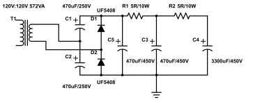
Here's the PSU I built for my monoblocs...
This is overkill for a class A amp, but 100W AB1 will prevent unwanted voltage sag in the PSU. This is usually desireable in a guitar amp, but sounds like du marde in a hi-fi amp.
BTW this power supply drops less than 10V at 400ma idle @ 320V.
Since you aren't using tube rectification, you can use smaller resistors and larger caps.
Here's the PSU I built for my monoblocs...
This is overkill for a class A amp, but 100W AB1 will prevent unwanted voltage sag in the PSU. This is usually desireable in a guitar amp, but sounds like du marde in a hi-fi amp.
BTW this power supply drops less than 10V at 400ma idle @ 320V.
Attachments
Last edited:
The "full wave" voltage doubler idea kodabmx suggested is the route to high performance at modest expense.
A Triad N-68X, which works in both "120" and "240" VAC zones, will yield slightly more than 100 mA. of B+ and that's enough for a stereoblock employing triode wired SE "12" W. multi-grid O/P tubes.
UFnnnn diodes are among the very best PN parts, in terms of minimum amount of switching noise production. However, zero switching noise is better than low switching noise and this Schottky diode is my suggestion.
Large valued cap. I/P filters generate ripple overtones, which must be filtered out. ALWAYS use a LC reservoir section. When the initial capacitance is gargantuan, the noise extends up into RF range. Scan the archives for my posts about "hash" filters.
IMO, the 12AU7 is a poor choice, as its μ is likely too low and, even more important, the fact that the type is non-linear. 😡
Much of what is being discussed here overlaps the discussion in this thread. I will ask the moderators to consider merging the 2 threads together.
If you can get some 12AT7s an RH84 would be a great option IMO.
I used the RH84 a lot for inspiration, so good to know I'm on the right track there.
Those speakers aren't very efficient, and I think you'll find a SE 6V6 amp to be pretty small, even for nearfield.
Just my 2 cents.
Just my 2 cents.
Traditionally, that's how power supplies were built.
Since you aren't using tube rectification, you can use smaller resistors and larger caps.
Here's the PSU I built for my monoblocs...
This is overkill for a class A amp, but 100W AB1 will prevent unwanted voltage sag in the PSU. This is usually desireable in a guitar amp, but sounds like du marde in a hi-fi amp.
BTW this power supply drops less than 10V at 400ma idle @ 320V.
Ah, very helpful. I was reviewing Blencowe's page on B+ Filtering - The Valve Wizard. As I understand it, the rectified signal should be DC. So a low pass filter as close to 0 hz as possible would be optimal. frequency = 1 / (2 pi R C).
So a typical B+ filter stage I'd use in a guitar amp would be a 4.7k dropping and a 32uf filter cap.
1.05hz = 1/(2*3.14*4700*32e-6)
However placing an RC filter in front of the B+1 node requires the entire current of the amp to flow through that dropping resistor. So a 4.7k resistor with 100ma+ of current will create a big problem. 100ma of current through 4700 ohms of resistance is a 470 volt drop.
So the solution is to drop the resistance significantly. This will prevent meaningful voltage drop and it will not require such an unreasonably high powered resistor. The resistor and capacitor values are multiplied by one another, so decreasing one while increasing the other offsets the frequency.
i.e. if I drop the resistor down to 470 ohms and the capacitor up to 300uf:
1.12hz = 1/(2*3.14*470*300e-6)
Is there a guideline for the high end of that frequency cutoff point? For example say I use a 470r + 100uf combo.
3.38hz = 1/(2*3.14*470*100e-6)
Also please correct any mistakes in the above reasoning. I'm learning.
That PT is quite affordable. I have a PT on hand salvaged from a guitar amp meant to power two 6V6's in push pull and a few 12AX7's that I think might be workable for this project.The "full wave" voltage doubler idea kodabmx suggested is the route to high performance at modest expense. <snip>
Would you avoid using any 12a*7 tube for the driver stage in this circuit? I have some 12AX7s and a few 12AT7s on hand I could make use of.
Sounds like I need to just bite the bullet and buy a choke. Thanks for the input.
Those speakers aren't very efficient, and I think you'll find a SE 6V6 amp to be pretty small, even for nearfield.
Just my 2 cents.
Perhaps Kegger's KT88 is the ticket.
Those speakers aren't very efficient, and I think you'll find a SE 6V6 amp to be pretty small, even for nearfield.
Just my 2 cents.
I have heard that concern raised elsewhere on se amps. My current thought is that I'll build it and see how it works. I've been considering upgrading those speakers anyways, so perhaps this would give me reason to do that - rather than building a beefier amp.
Sounds like I need to just bite the bullet and buy a choke.
A decent enough choke can be had for not much money. A Triad C-7X sells for less than $13. Don't worry about the 90 mA. rating. When 100 mA. are pushed through the part, saturation effects will reduce the inductance. 9 H. or thereabout will still provide effective filtering action. 😉 Given the substantial inductance, "normal" caps. in the doubler stack will be satisfactory and a "hash" filter should not be needed. 2X 120 μF. parts in the doubler stack will give performance equivalent to a true full wave rectifier working into 60 μF. That should be plenty. Remember, a 150 mA. rated 6CA4/EZ81 vacuum rectifier is limited to a 50 μF. 1st filter capacitor.
Block potential turn on surge damage to the rectifying diodes and also prevent magnetostriction induced power on clanging, by inserting a CL-140 inrush current limiter in the line between the power trafo and the "center" of the doubler stack.
I used the RH84 a lot for inspiration, so good to know I'm on the right track there.
If you have a pair of used guitar OTs, they would probably work OK in an RH84.
I've built RH84s with console stereo OTs that looked pretty small and 'basic' and they sounded OK to the folks that got the amps.
But IMO Edcors are a better choice that guitar amp iron if you don't have something in the parts bin already, and have to make a purchase.
I think an RH will have plenty of output for listening at your computer work station, unless your DAC has very low output.
Perhaps Kegger's KT88 is the ticket.
I like the Kegger KT88 design, but even it is a bit small. Technically the speakers mentioned would be better off with a big SS amp. That said, with near field listening at low levels, it might be okay, and the OP mentioned he was thinking about upgrading speakers anyways.
Just to throw out an idea , a SE 6L6 build would not be all that much more expensive than a SE 6V6 build. All depends on what you are looking for in terms of power.
The "full wave" voltage doubler idea kodabmx suggested is the route to high performance at modest expense.
A https://www.mouser.com/datasheet/2/410/media-1067757.pdf
i use this all the time whenever i could, and since i wind my own traffos, making them to any voltage is no problem for me.....
the pioneer SA-81 that i serviced a few years back used this psu topology...
so did the legendary Harman Kardon Citation 2.....
So a typical B+ filter stage I'd use in a guitar amp would be a 4.7k dropping and a 32uf filter cap.
1.05hz = 1/(2*3.14*4700*32e-6)
In my example, the final filter is 5R/3300uF. This is roughly 10Hz and it works fine, no hum to the speakers, however I'm using this only for B+ for the push pull output stage. PSUD2 says that filter has 124mV of ripple at 318V. Push pull has CMRR, SE does not. Whether or not 124mV is low enough hum I don't know, but I would assume you'd need to put your ear in the woofer to hear it.
- Status
- Not open for further replies.
- Home
- Amplifiers
- Tubes / Valves
- Advice on Hifi Build for a Guitar Amp Builder