Hi all, hope you will share your experience with a newbe 🙂
I'm in the process of building my 5'th hifi setup of my life, and is old enough so the surround and Atmos is in the history book. So my current project is to merge old school with modern technology. I mainly listen to piano, jazz and a little blues, and typically at very modest volume levels.
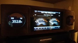
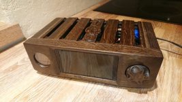
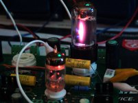
So far I have completed step 1 building a RPI based streamer/DAC/preamp based on Audiophonis modules, a oled screen, oak from my granmothers old table, my cnc router and many hours. Pictures attached.
So now the power amp project is in the design phase, plan is to go a similar route as the DAC streamer by buying HW modules and crafting the cabinets, and in that way get a relatively "safe" end result.
The plan is to build 2 mono block amps, based on a PP KT88 setup with a power target of 40-50W, capable of driving a 8ohm dual 12" + full range open baffle speaker setup.
And now for your assistance, can you advice me if this design is "a safe middle way" for the above situation.
Tubeland KT88 PP kit with auto bias regulation
toroidy OPT 6,6kohm with UL and cathode feedback
toroidy Mains trafo 220v-> 400V1.1A, 60V0.1A, 9V2A, 6,3V5A
Tubes will be KT88 and ECC82
My major question right now is the choice of OPT and voltages for the mains trafo.
Links:
KT88 PP Mega BS
TTG-CFB6600PP - Tube output CFB transformer [6,6kOhm] Cathode Feedback Push-pull - Shop Toroidy.pl
Thanks for your advice
I'm in the process of building my 5'th hifi setup of my life, and is old enough so the surround and Atmos is in the history book. So my current project is to merge old school with modern technology. I mainly listen to piano, jazz and a little blues, and typically at very modest volume levels.
So far I have completed step 1 building a RPI based streamer/DAC/preamp based on Audiophonis modules, a oled screen, oak from my granmothers old table, my cnc router and many hours. Pictures attached.
So now the power amp project is in the design phase, plan is to go a similar route as the DAC streamer by buying HW modules and crafting the cabinets, and in that way get a relatively "safe" end result.
The plan is to build 2 mono block amps, based on a PP KT88 setup with a power target of 40-50W, capable of driving a 8ohm dual 12" + full range open baffle speaker setup.
And now for your assistance, can you advice me if this design is "a safe middle way" for the above situation.
Tubeland KT88 PP kit with auto bias regulation
toroidy OPT 6,6kohm with UL and cathode feedback
toroidy Mains trafo 220v-> 400V1.1A, 60V0.1A, 9V2A, 6,3V5A
Tubes will be KT88 and ECC82
My major question right now is the choice of OPT and voltages for the mains trafo.
Links:
KT88 PP Mega BS
TTG-CFB6600PP - Tube output CFB transformer [6,6kOhm] Cathode Feedback Push-pull - Shop Toroidy.pl
Thanks for your advice
Attachments
IMO, Octal sockets on printed circuit boards (PCBs) are a bad idea. The forces associated with Octal tube insertion/removal easily crack the substrate and/or damage traces. 😡
Something like a 3.2 Kohm to 3.6 Kohm primary O/P transformer is "normal" with KT88s.
The 12AU7/ECC82 is non-linear. Either 6FQ7s or 12BH7s are better.
Something like a 3.2 Kohm to 3.6 Kohm primary O/P transformer is "normal" with KT88s.
The 12AU7/ECC82 is non-linear. Either 6FQ7s or 12BH7s are better.
Last edited:
My advice is start simple, pull the KT88 datasheet which might give you your OPT pri Z etc then draw some load lines, this will give you your rough HT/B+. Rather than do simulations I knock the OP stage upon the bench with a temporary power supply and do some testing.stick to either fixed or cathode biased for now, then you can go back and chuck in autobias if you really must, I don't think they're needed,but each to their own.
Layout is all important, stick to P-P wiring and use standard valve bases for the reasons Eli mentioned + P-P is more flexible, you will need to make changes so don't bend leads round tags etc too securely, just tack in components and wires for now.
Andy.
Layout is all important, stick to P-P wiring and use standard valve bases for the reasons Eli mentioned + P-P is more flexible, you will need to make changes so don't bend leads round tags etc too securely, just tack in components and wires for now.
Andy.
IMO, Octal sockets on printed circuit boards (PCBs) are a bad idea. The forces associated with Octal tube insertion/removal easily crack the substrate and/or damage traces.
That was true 50 to 60 years ago. Today, a properly designed and well made PC board will not fail with octal, compactron, miniature, or even 4 pin 300B sockets in it. Traces to the tube sockets should be 50 to 100 mils wide and large annular rings should be used during layout.
I have been selling these PC boards for 15 years and have never seen a PC board failure at the sockets. These three have served as some of my test boards. They get used for experiments, some of which don't end so well. The SSE has seen many blown electrolytic caps. It gets cleaned with alcohol, and reused. The TSE is Tubelab board #1, the first ever commercially fabbed Tubelab PC board. It served as a test mule for several years early on. All are between 11 and 15 years old, and have seen lots of tube insertions.
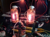
The sockets will fail long before the board will. The SSE board in the picture has had at least 3 sets of output tube sockets. It can be seen here undergoing some "extreme duty testing" almost 12 yeas ago.
A pair of cheap "NOS" tubes sold to me by AES were obviously well used when I got them, so I decided to subject them to some extreme testing. Yes, you can get 15 watts from a 6BQ6GT in SE....for about 10 minutes.
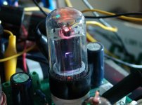
These 6V6GTA's were from of a NOS sealed bulk packed box of 100 that I personally picked up at a NASA auction in Florida 12 years ago. About 25% were bad, with milky or missing getters. Most that remain today have since gone gassy. I "tested" some of the gassy tubes in my trusty SSE board 12 years ago. A runaway led to a vented cathode bypass cap, which was replaced with the 100 volt caps that are still in the board today.
PC boards from the past were indeed pretty bad, especially the brown phenolic stuff from the 1960's. Todays FR-4 will take all you can throw at it without issue. Extreme heat can darken or discolor the board, but that is usually not harmful. I recommend that hot parts like 5 watt cathode resistors be spaced 1/4 to 1/2 inch off the board for proper air flow.
The tube sockets are best replaced by cutting the old one out with a sharp pair of cutters, cutting each pin at the base of the socket. Then remove the pins from the board, one at a time. Clean out each hole with solder wick, and put in a new socket.
Attachments

You can heat-damage today’s FR4 boards enough to make them partially conducting - eventually. It takes some doing, not just a little discoloration. You pretty much have to turn it *black* - and that takes multi-hundred or thousand watt solid state amp with shorted output transistors. And some resulting fire from 5 watt emitter resistors dissipating several hundred watts. They can conduct much more current than a runaway tube, and the power supplies used can deliver 50 or 100 amps into a short. Tube amp transformers can’t deliver that kind of current.
Boards from yesteryear would get partially conducting if they just look a little “cooked”. And traces peeled off just recapping, let alone replacing dead output transistors. Especially so if the board got cooked. I wonder if that’s why a lot of compaction horizontal sweep tubes are only rated at 200 or 220 C bulb temp rather than the 250 for audio tubes, and dissipation numbers were typically lower for a given size plate. They used those old phenolic PC boards back in the day, and the whole TV had to be reliable and serviceable.
Boards from yesteryear would get partially conducting if they just look a little “cooked”. And traces peeled off just recapping, let alone replacing dead output transistors. Especially so if the board got cooked. I wonder if that’s why a lot of compaction horizontal sweep tubes are only rated at 200 or 220 C bulb temp rather than the 250 for audio tubes, and dissipation numbers were typically lower for a given size plate. They used those old phenolic PC boards back in the day, and the whole TV had to be reliable and serviceable.
Hi all, thanks for your various feedback.
I work in the electronic industry and PCB based will not be any issue. As mentioned is a proper designed FR4 board not of any strength concerns.
I'll take the advice regarding preamp tubes, but I need further advice on the choice of OPT and B+. From the studies I've done so far do it seem that a 3-4kohm give higher wattage, but less damping. If you have and links tpo articles discussing the compromises regarding OPT parameters then please let me know.
Same goes with B+ voltage.
And I'm trying to avoid to much trail and error, but would prefer to construct a "safe middle way" for this build. Then experiments can come later on 🙂
Lots of good stuff regarding load matching for tubes on Patrick Turner’s site ...
pt 1 triode load matching
He is a big fan of the KT88.
pt 1 triode load matching
He is a big fan of the KT88.
Hi Guys
Had been studying a bit, but can you verify if I got the compromises correct on a monoblock with the following setup:
preamp and splitter tube = ECC82/12AU7 JJ
Power Tubes KT88
4k or 5k OPT ? I guess 5k will be fine for 50W pentode operation
TTG-CFB5000PP - Tube output CFB transformer [5kOhm] Cathode Feedback Push-pull - Shop Toroidy.pl
Intended for Push-Pull CFB
Core type Toroidal
Ultralinear tap 33%
CFB Windings 10% Ra
Nominal Power 80W
Nominal anode current 300mA
Frequency bandwidth (-3dB) 16 Hz - 91 kHz
Secondary Impedance 4 and 8 Ω
Primary Impedance 5 kΩ
Turns Ratio (Np:Ns) 35,36:1 (4Ω) , 25,00:1 (8Ω)
Primary Inductance Lp 567 H
Primary Leakage Inductance Lsp 4,83 mH
Total Primary DC Resistance 65,5Ω
Effective Primary Capacitance 2,1 nF
For the net trafo's can yo uverify the following voltages ?
Prim 230V50Hz
Sec I 353VAC 0.55A
Sec II 60VAC 0.1A
Sec III 9VAC 2A
Sec IV 6,3VAC 5A
Any advice is welcome
The 12AU7/ECC82 is non-linear. Don't use it for voltage amplification.
Mullard style circuitry is less finicky than Williamson style.
Protect the O/P "iron" core against saturation by placing a 1 pole high pass filter at the unit's I/P. F3 should be in 16-18 Hz. range.
Mullard style circuitry is less finicky than Williamson style.
Protect the O/P "iron" core against saturation by placing a 1 pole high pass filter at the unit's I/P. F3 should be in 16-18 Hz. range.
12BH7 is linear.
So is the 6CG7 / 6FQ7 since they are 9 pin versions of the 6SN7.
Simple way to get 75 WPC in TRIODE with KT88's. Use a 5K OPT to get about 50 watts, or a 6.6 K OPT with a bit over 450 volts for 50 WPC in triode.
The same amp wired in pentode mode made over 100 WPC with the power supply turned up a bit.
Tubelab Universal Driver Board, 2015 version
Follow the link in the first post for a detailed blow by blow design effort from opposite ends of the world.......it is a long but informative thread.....and, no you don't have to use 6L6GC's.
I have stuck anything from tiny 50C5 radio tubes to big transmitting tubes into my test amp....no 6L6GC's though. I trust the design well enough to stick some priceless NOS JAN GE 6550A's in it and crank them up:
75 watt per channel triode mode tube amp prototype - YouTube
If you really believe that PTP wiring is better, the schematic is in the second post.
My personal choice in a KT88 amp would either be the JJ ECC99 or 6N6P as a phase splitter.
The amps ive build i used a mix of fixed bias with a cathode resistor to provide more stability, as the person i was building the amp for didn't adjust the bias at all so a fixed bias amp was out of the question.
A little tube regulator running a fifth KT88 was used to supply the preamp stage.
As for the PCB, i have noticed that Belton octal PCB sockets are quite reliable. I am working on a 6SN7 KT88 PP board right now if you want the eagle files for that.
Last edited:
- Home
- Amplifiers
- Tubes / Valves
- Advice for Monoblock KT88PP build