All,
I am curious as to the benefit of 2 diode bridges in a stereo amplifier using a single transformer. I understand that 2 separate transformers is considered beneficial because any power requirements on one side will not affect the other side. This reasoning would seem to assume that there is excess available current at the primaries of the transformer, but there is not excess current at the secondaries, thus any large draw on one side will cause a change in the available supply to the other side, i.e. a large draw from one side will cause a dip in voltage at the secondaries which in turn will affect the second side. Is my reasoning correct so far?
But is the bottleneck considered to be the transformer? Or is it the diode bridge? I ask this because I notice on my Hafler XL280 that a single transformer is used with 3 diode bridges--as far as I can tell 1 each for the output stages left and right, and one for the circuit rails. If the two diode bridges help to minimize the impact of the channels on each other, it would seem to indicate that the diode bridge, and not the transformer is the source of the bottleneck. Is this the case? Or what advantage does the 2 or 3 diode bridges bring to the power supply design with a single transformer?
Thanks for any insight that can be offered.
Ron
Once upon a time, a journalist asked Rockefeller:
" How much is ENOUGH ? "
" Just a little bit more " - replied Rockefeller.
The same goes for rectifier bridges. Look at the problem this way: The audiophiles "dream" is to have two totally separate mono-blocks. But these cost $$$$$. And weigh heavy kilograms.
So ... What is the "next best thing"?
The next best thing is to have the bulky, expensive and heavy part shared (the iron transformer), but then ... fork out to the left and to the right. The earlier, the better, some say.
Some will argue that a single bridge will be perfectly competent to power a whole amplifier. But that means that the WHOLE of the current will be passing through that single bridge. Which, BTW, is a fairly CHEAP item on your BOM. So, if one dollars worth of added cost on the BOM does not make a hell of a difference, then why not use more than one bridge?
You fork out earlier. To the left and to the right. You get better separation. And also, what is very important, the heat dissipation of each individual bridge is now halved. Lower. Possibly, the dropout voltages are slightly smaller. And, with the current halved, the filtration on the capacitor bank is somewhat easier and more effective. And: geographically more "local" to the respective channel, as opposed to "central" and "far away" from the respective channel (left / right).
...
The other interesting question, that also need be asked is:
Are these separate bridges in your XL280 powered from the SAME secondary winding, or is there a separate winding dedicated for EACH of the bridges? Because if you have separate windings, it would be a gross sin and design negligence not to use them in such a split "as-early as possible" manner / way.
With multiple secondary windings, the only thing that remains common for the left and right channels is the ... magnetic flux flowing around the transformers core. In other words: almost as good as dual mono, or mono-blocks, but without the extra kilograms and the extra chassis and the extra $$$$.
But even such an "almost" - can make a huge difference. IMHO.
Last edited:
OK, so in short, there is some benefit, and the cost is not much so why not do it. That makes sense. I'll post the schematic for the power supply--you see that there are two secondaries available , but it seems in this design they use one for the output stage of both sides, and use the other to feed the rails only. I guess they consider that "first watt" as more critical than independent L/R. Am I properly understanding the schematic?

Attachments
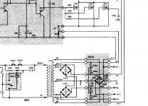
There is one high current power supply, rectifier and capacitors, for each channel's output stage. The third power supply, rectifier and capacitors, is for the low current front ends and is used for both channels. The AC input for this low current rectifier is taken from the ends of the secondary winding and is probably only a few volts more than the high current voltages.
Craig
Craig
The diode bridge is not so expensive, but the ecaps are and the extra space.
If you double the shared capacity does it work out to be about the same as having them separate but of the same total size?
I am not too sure about cross talk, what the improvement would be, if it mattered. I guess it depends on the PSRR of each channel.
If you double the shared capacity does it work out to be about the same as having them separate but of the same total size?
I am not too sure about cross talk, what the improvement would be, if it mattered. I guess it depends on the PSRR of each channel.
Yes, as mentioned in #4.
You have an interesting transformer, with an interesting multi-tap secondary, comprised of:
a). RD/YW: The center tap, which is used as the center ground reference, for all three symmetrical power supplies (from what seems to be visible on the graphic).
b).
c). The upper and lower RD taps, "mid-height", working out-of-phase; These taps are forked left and right, into two independent rectifier bridges: DB301 and DB302. From here on, you have independent symmetrical filtering caps, and then rails for each channel. These are the high current, but slightly lower voltage supplies for the current hungry power transistors.
d).
e). But hey, you ALSO have the upper and lower BE taps of the secondary; providing a slightly higher voltage. They go to the third bridge, with yet separate filter capacitors associated therewith. This is a symmetrical, higher-voltage, but lesser current, power supply for the drivers and the front end of your amplifier. It seems that in order to maximize the output swing to maximum extent possible, these higher rails are used to power the driver transistors, which in turn drive output transistors, so as to achieve the highest possible output signal swing. Very nice concept.
#5: Valid argument: You split the power hungry symmetrical rails; Separate set for Left. Separate set for Right. Each rail current is now half the current, as compared when they would be shared by left/right; so you probably can "get away" with slightly smaller valued capacitors in each branch; But this also means that you have two independent sets of such supplies, so you need twice as much capacitors; and twice the space; Which will probably turn out to be similar or even slightly more in terms of $ spent and total volume/weight of the capacitors; Is it worth it? Probably yes. IMHO. Separation.
Last edited:
......any large draw on one side will cause a change in the available supply to the other side...
Is this a guitar amplifier? (stereo?)
In HI-FI we probably should not find sag in the power transformer on un-clipped speech/music signals.
Put a voltmeter on your amp supply (do NOT let it short!!) and watch it when you play loud.
It is not unusual in some amps worked FULL power to see a 30% drop from idle voltage. Clean music should then be 3% drop at worst.
Now-quite-affordable main caps supporting FULL sine power have a half-second time constant; music peaks are much shorter.
I have seen amp designs where a small dip in supply upsets the amp bias; this can easily be designed against.
True.
I would even go a step further. First, set the volt meter for the DC voltage range and observe the sag under full power load into a dummy load. The sag on the DC, rectified and filtered rails.
Now, switch to the AC voltage range, and try to observe sag directly on the AC output terminals of the secondary of the transformer. Try, as in good luck.
The thing is that the effective impedance of the secondary of the transformer, as observed directly on the secondary output terminals, is probably even lower than the impedance on the output of the DC rails after the rectifiers and filters.
Provided that it is not just a guitar amp, but a reasonable quality Hi-Fi amplifier, where the transformer is chosen to required specifications or slightly over-sized, with no skimping.
This power supply shown is for a Hafler XL280 HiFi amplifier. I also have a DH200 with a very standard supply (single diode bridge) and a DH500 with a modded dual-toroid supply.
I have the means to measure AC and DC voltage and save the data into a spreadsheet. Maybe I will try to measure at different points under different loads to see what's happening with these amps. I can only measure DC up to 24 volts, but could maybe make a voltage splitters with high impedance in order to get a relative measure of sag under load for the DC part.
I have the means to measure AC and DC voltage and save the data into a spreadsheet. Maybe I will try to measure at different points under different loads to see what's happening with these amps. I can only measure DC up to 24 volts, but could maybe make a voltage splitters with high impedance in order to get a relative measure of sag under load for the DC part.
As long as you have a hefty resistive dummy load, on some big chunk of heat sink. It would be hard to imagine to drive this thing to full power and not loose / damage your ears, if working into a true loudspeaker.
True.
I would even go a step further. First, set the volt meter for the DC voltage range and observe the sag under full power load into a dummy load. The sag on the DC, rectified and filtered rails.
Now, switch to the AC voltage range, and try to observe sag directly on the AC output terminals of the secondary of the transformer. Try, as in good luck.
The secondary current and voltage are complex waveforms due to the heavy conduction pulses through the rectifiers - only a 'scope can show whats really going on here, and ideally look at the current waveform too, not just voltage, to see the details of the conduction pulses.
- Status
- Not open for further replies.
- Home
- Amplifiers
- Power Supplies
- Advantage of 2 diode bridge in stereo amplifier