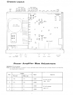
On the bias adjustment section in step 4 it says to measure between 2 and E2 but there is no 2 and E2 anyware on the schematic above. What should. I measure? Also I don't have 8ohm loads as it requires should I run it with no load. For a while or connect it to my 6ohm speakers? Moreover in the warm up period do I need to have an input connected?
It's a rotel ra-840bx4. Here is the service manual ROTEL RA-840BX4 Service Manual download, schematics, eeprom, repair info for electronics experts
It's a rotel ra-840bx4. Here is the service manual ROTEL RA-840BX4 Service Manual download, schematics, eeprom, repair info for electronics experts
Attachments
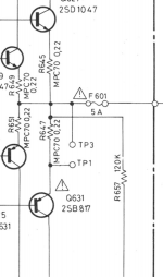
Between TP1 and TP2 in other words across R647, identical for the other channel.
No signal conditions and no load.
and it should be 0V? The other channel you mean beteween tp3 and tp4?
The TP3 and TP1, TP4 and TP2 are for measuring and setting the bias. Check it, makes sure it close to the 15mV and then let the amp warm-up for 15-30 minutes. Then set it for the final time at the 15mV (between 10-20 is close enough)
1 and E1, 2 and E2 (looks to be right below the direct speaker outputs) should be the speakers (you can use the speaker posts red and black with coordinating DMM probe) as that is measuring the DC offset, which is why it should be 0mV (anything <15mV is really good though)
Go slow of the bias - if you start to high it could go into thermal run-away and possibly burn outputs.
The TP3 and TP1, TP4 and TP2 are for measuring and setting the bias. Check it, makes sure it close to the 15mV and then let the amp warm-up for 15-30 minutes. Then set it for the final time at the 15mV (between 10-20 is close enough)
1 and E1, 2 and E2 (looks to be right below the direct speaker outputs) should be the speakers (you can use the speaker posts red and black with coordinating DMM probe) as that is measuring the DC offset, which is why it should be 0mV (anything <15mV is really good though)
Go slow of the bias - if you start to high it could go into thermal run-away and possibly burn outputs.
E1 and 1 is kinda weird it looks like E1 is the ground cable coming from the powersupply. I did set everything on almost 0(keep in mind my multimeter is kinda bad) but i put the bias on 2.5mV as the manual states. Do you recommend me to raise it a bit towards 10-15mV? Why is that? Will it run hotter and maybe a bit more powerful this way? This amplifier is really old and it has leaky power capacitors, at high volumes it clips really bad(i guess thats the fault of the falling caps) so I want to make it as reliable as possible until I change the caps.
I mis-types or read. I usually use 15mV as the typical for BJT. Set it as the schematic says and judge the heat for yourself - should be pretty low at that setting. No additional power to be had by raising the bias.