With the help of the boards here, I was able to correct a distortion problem with a seriously flawed OTL headphone amp. One of the other pieces of advice was for me to set up NFB running from the cathode of the 12ax7 to the output. That would lower the output impedance from about 280r to 40r. The load for this amp is a pair of Sennheiser HD-580's.
I did just that with a 12k reisistor and it sounded AWFUL. With no NFB, the amp sounded just fine. A bit dark, but fine. When NFB, the bass dissapeared, the high's sounded recessed and smeared, and the mids were very emphasized.
Why would that happen? I thought that adding some NFB lowered the output impedance and would help "tighten" the sound? If it sounds good enough, should I even be worried about the high output impedance?
Attachments
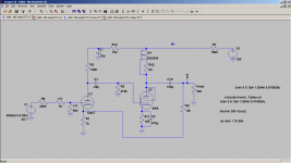
It probably has nothing to do with feedback. What you did was connect up the DC bias voltage of the 12AX7 to your output. You probably have a few millivolts or so DC on the output now. You need a large capacitor between the output and the 12k feedback resistor to block the DC from the 12AX7 cathode. The DC will really mess up your headphones.
What about landing the 12k feedback resistor before the 100uf DC coupling cap?
If you do that, then the plate voltage shows up at the 12AX7 cathode, which is a very bad thing. You need to separate the DC from the AC by using a capacitor or other device like a transformer.
Member
Joined 2009
Paid Member
I'm really not familiar with tube circuits, but I wonder if global feedback is what you want here at all - there may be other factors affecting the bass which you can influence instead. The power supply is often an important factor, capacitors, tube operating points etc. Lower output impedance only gets you so far.
edit: global feedback with capacitors in the loop introduces a risk of low frequency oscillations if not 'done properly'.
I've no experience to draw on here, but could you re-configure your output stage so that instead of using a constant current source as the plate load, you made it into a hybrid mu-follower where the plate load uses the FET as a source-follower (which 'looks like' a constant current source to your output tube too). This will have a low output impedance; it is local feedback at the output stage itself.
Last edited:
Another 100uF would be so large that it would prevent any "motorboating". I can't do the math in my head to give you an exact size.
I guess I'm asking if this amp can be salvaged or turned into something useful.
I already know that the design (it's a one-off Antique Sound Labs product) is pretty bad.
I already know that the design (it's a one-off Antique Sound Labs product) is pretty bad.
Another 100uF would be so large that it would prevent any "motorboating". I can't do the math in my head to give you an exact size.
That would work. I have a few of those on my workbench.
It's not a terrible design at all. It could be improved, but that depends on how much money you want to spend.
Member
Joined 2009
Paid Member
Try this for further information on my suggestion: http://www.diyaudio.com/forums/headphone-systems/73169-mu-follower-hybrid-headphone-amplifier.html
Try this for further information on my suggestion: http://www.diyaudio.com/forums/headphone-systems/73169-mu-follower-hybrid-headphone-amplifier.html
I've read that thread while researching how to improve my own design. Since I have the DN2540 as my CCS plate load, I wouldn't need the zener for a bias source. So, to do that I think I would only need to move my output to the source of the FET, off of the anode. Is my understanding correct? That's what 00940 recommended in another thread.
Member
Joined 2009
Paid Member
No, you need to do a little more work than that, but not too much. The gate of the FET needs to be given a dc bias supply that pins the source at a suitable voltage - in effect it sets the plate voltage for the output tube; then connect the gate to the anode via a capacitor which acts to separate the dc-bias you've applied to the FET gate from the dc-voltage on the anode. The same cap will ensure the gate receives the ac signal from the anode. A couple of resistors and caps and you're there perhaps.
There also needs to be enough current flowing through the FET so a power resistor from the FET source to ground maybe required if there isn't enough current being drawn through the output tube. Unfortunately, as I've never built one of these I have no experience to draw on. I'd be tempted to try and ensure enough current through the tube so I didn't have to add a power resistor.
It's more work than a big cap in a global feedback loop - maybe if you have the energy, try both options and see which you like best.
Last edited:
Hi,
If you feel it sounds fine then, I 'd leave well enough alone.
Still:
Put a second 100 microF cap in series with the one you already have and take the feedback from the midpoint in between the caps to the top of Rk of the 12AX7.
Ciao, 😉
If you feel it sounds fine then, I 'd leave well enough alone.
Still:
What size of cap would work there?
Put a second 100 microF cap in series with the one you already have and take the feedback from the midpoint in between the caps to the top of Rk of the 12AX7.
Ciao, 😉
My opinion is that you should change the output stage to a follower, DC couple the grid of the EL84 to the plate of the 12AX7, and increase the B+ to 250VDC or so. I think you only need 6 dB of gain at most for a headphone amp, usually less than that, so having two gain stages like this is not needed. The 12AX7 alone puts out plenty of gain by itself.
My opinion is that you should change the output stage to a follower, DC couple the grid of the EL84 to the plate of the 12AX7, and increase the B+ to 250VDC or so. I think you only need 6 dB of gain at most for a headphone amp, usually less than that, so having two gain stages like this is not needed. The 12AX7 alone puts out plenty of gain by itself.
This amp is on a PCB, so altering the output from a common cathode to a follower would be difficult to say the least. I've looked into simulating both of those options, which does give a good low impedance and plenty of power.
OK. I don't believe in putting tube circuits on PCB's, but that's another story.
It looks like you don't have much of any options with this thing then, unless you want to buy 4:1 output transformers. Those will cost you at least $80 each.
It looks like you don't have much of any options with this thing then, unless you want to buy 4:1 output transformers. Those will cost you at least $80 each.
OK. I don't believe in putting tube circuits on PCB's, but that's another story.
It looks like you don't have much of any options with this thing then, unless you want to buy 4:1 output transformers. Those will cost you at least $80 each.
Ugh. Just what I was trying to avoid. I'll try reconnecting the NFB with a 100uf cap in series to see if I get a good result. Otherwise, I'll probably leave it. I've had this little amp with all of its flaws for over 10 years and it still sounds pretty good to my ears.
Side note: I see you're in VA. Anywhere near DC? I live in NoVA.
- Status
- Not open for further replies.
- Home
- Amplifiers
- Tubes / Valves
- Adding NFB makes headphone amp sound AWFUL!!!