Hi,
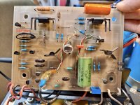
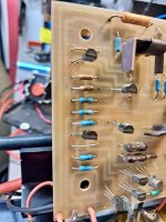
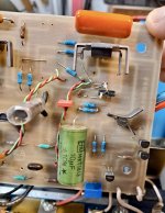
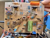
I have a Threshold S/500 Optical Bias. I have heard of some of these amps having an offset trimmer pot. I pulled the amp apart to replace the tantalum cap as well as the adjustment trimmer for the bias.
I thought maybe the 301 ohm resistor but I cannot be sure. My offset is right under 50mv but fairly stable. I would like to adjust it to close to 0mv
Attachments
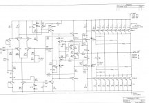
I have a couple. I have the S/500 optical. I have these two schematics. I think the first one is the S/500 non-optical and the second one is the S/500 optical series II. I am not sure if the series one optical, like I have is any different than the series II optical.
Anyways, maybe these will be helpful. I have had a hard time tracking down schematics for this amp. Thank you BTW!
Anyways, maybe these will be helpful. I have had a hard time tracking down schematics for this amp. Thank you BTW!
Attachments
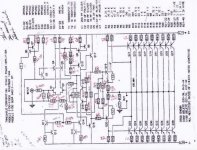
considering that you have (if those red marks are showing your actual amp) cap to GND from neg phase , setting of DC offset is of limited span
however, still possible
easiest and most secure way is to alter lightly current though input LTP
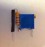
decrease R5 to 220R, put in series with R5 200R trimpot, connected as variable resistor (wiper shorted with one outer pin)
preset to 300R (R5+trimpot), power up, fiddle
however, still possible
easiest and most secure way is to alter lightly current though input LTP
decrease R5 to 220R, put in series with R5 200R trimpot, connected as variable resistor (wiper shorted with one outer pin)
preset to 300R (R5+trimpot), power up, fiddle
Okay I will give that a shot. I have a 470 ohm 25 turn trimmer. Do you think that will do in line with the 220r? I can order a 200R
Thanks!
Thanks!
it'll do
leaving 200R in, as fixed resistor is safety measure, preventing gray smoke (overcurrent)
I=0V65/R
leaving 200R in, as fixed resistor is safety measure, preventing gray smoke (overcurrent)
I=0V65/R
I wanted to post that I did the offset pot and resistor combo and it worked out well. R5 goes from the negative rail so if you have the PCB to mine, this is the one you want to do (first picture). There isn't a ton of adjustment that is possible but if you're within the 50mv tolerance, you will be able to adjust it to around 0. I used a 180ohm resistor and a 470ohm pot. I will order a dale resistor and proper trim pot with next mouser order (always a order to do)
I ended up with around 345 on one channel and and around 322 on the other. The resistance can be measured in circuit but you have to remove the leads to positive main cap.
I ended up with around 345 on one channel and and around 322 on the other. The resistance can be measured in circuit but you have to remove the leads to positive main cap.
Attachments

- Home
- Amplifiers
- Pass Labs
- Add a Theshold S/500 offset Pot